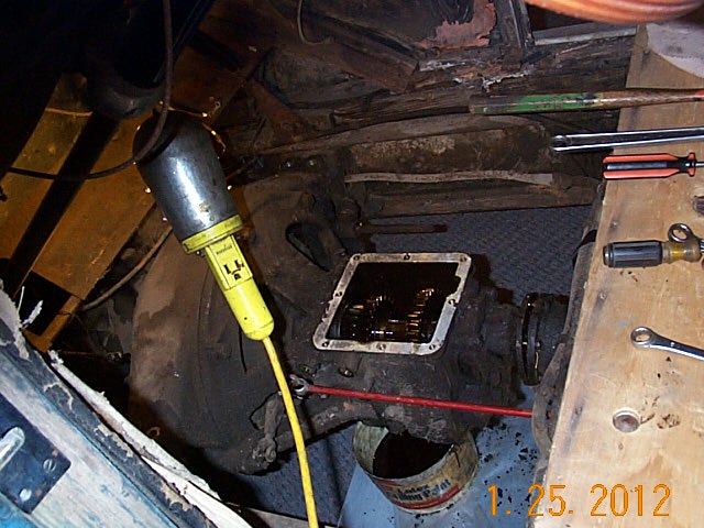
So I just took the trans cover off, which gave plenty of room to fit the trans assembly under the firewall.


Page 2.
1925 Hudson Super Six Biddle and Smart 7 Passenger.
Engine and other mechanical work.
On to Page 3 Interior and Body Work
Back to Page 1 of pictures.
Click on pictures for larger version.
Jump to:
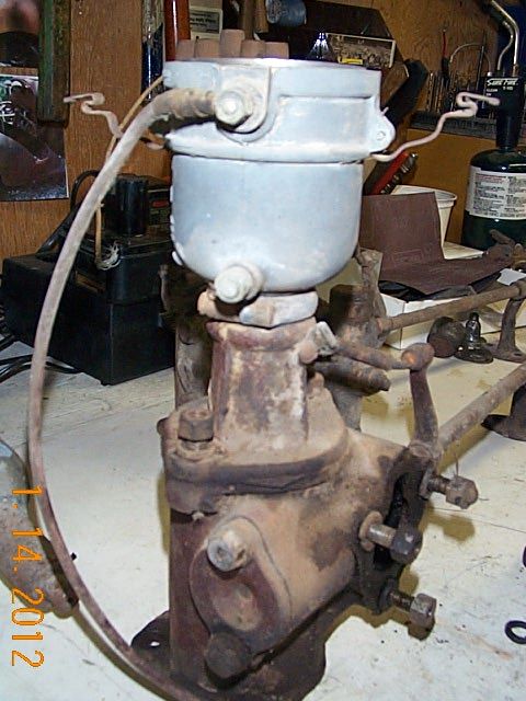
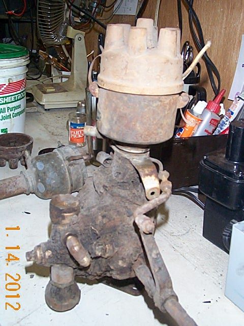
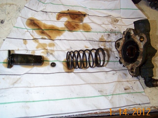
Distributor -
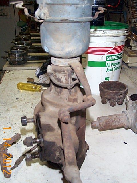
Oil Pump -
Starter, Generator -
Water Pump -
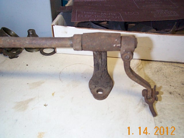
Steering -
Fuel System -
Clutch -
Transmission -
Rear Axle -
Wheels -
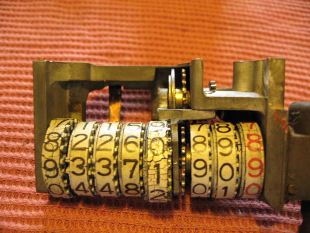
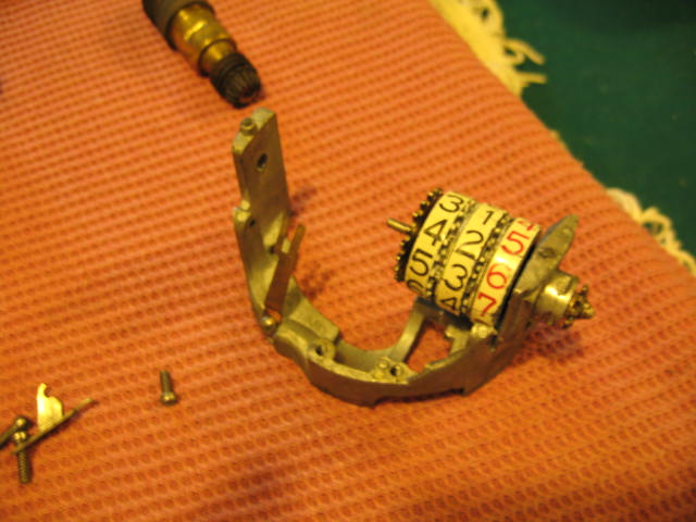
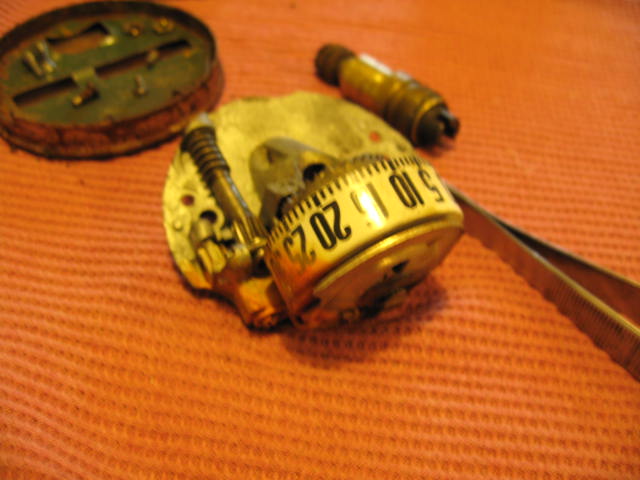
Speedometer -
Lights -
Exhaust -
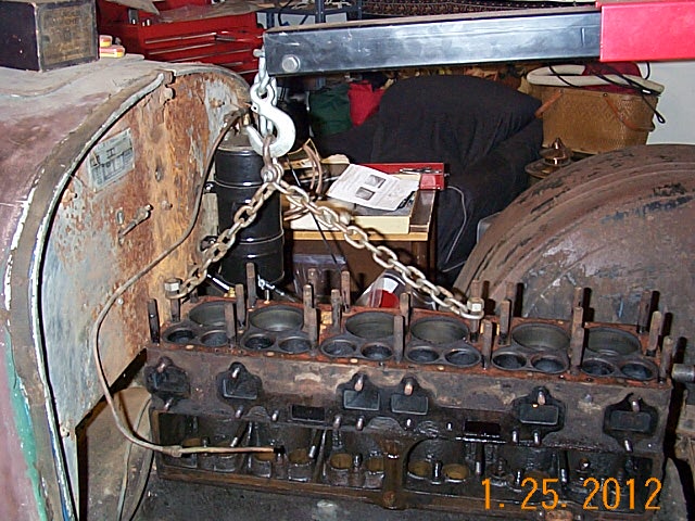
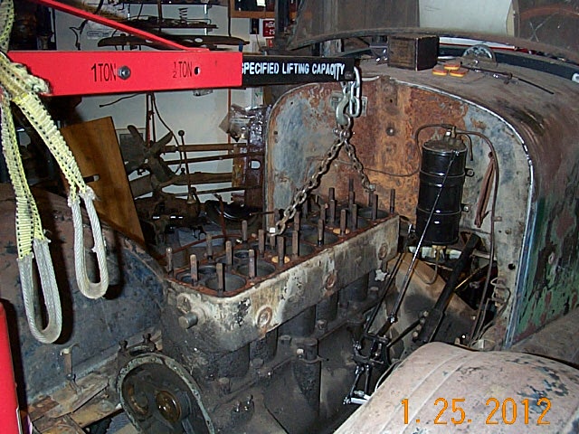
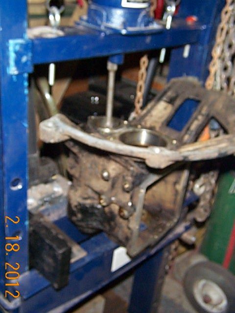
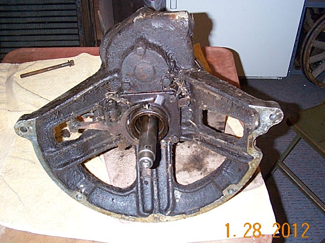
Pulling out the engine, transmission assembly. It is hard to drive the pin out of the bell covering the shifter tower.
So I just took the trans cover off, which gave plenty of room to fit the trans assembly under the firewall.
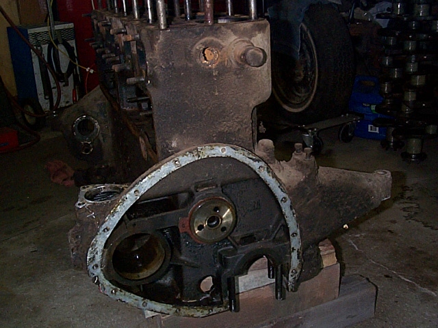
Tear down of my extra engine. This turned out to be a very good engine, I do not have to bore, or do the bearings.
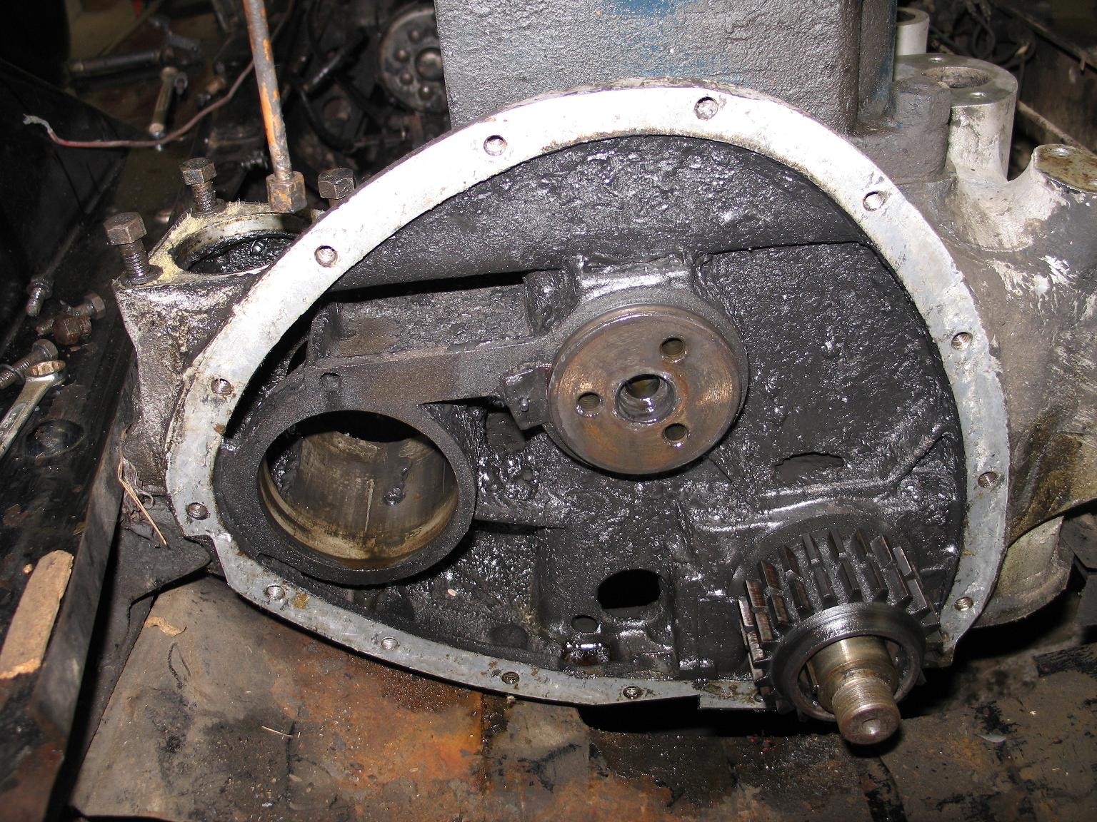
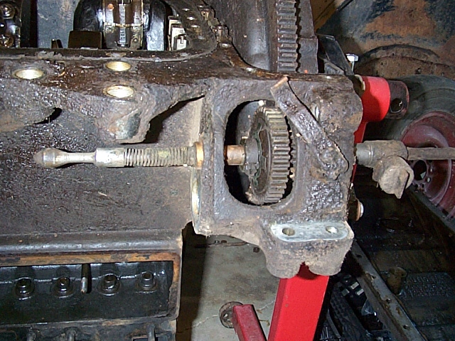
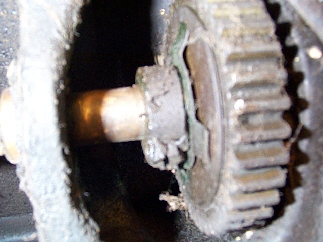
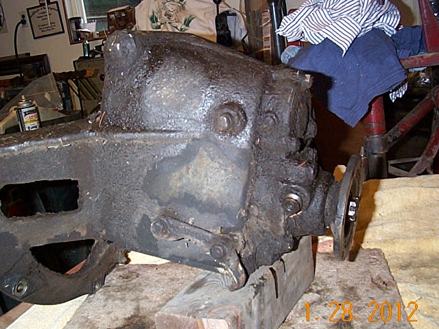
Front of Engine.
![]()

Assembly.
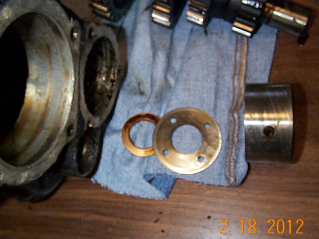
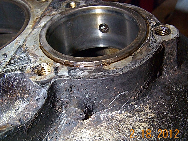
Fitting the chain adjustor with an O-Ring. When you use a gasket it takes a set and hard to break loose.
I used a die grinder with 45 degree cutter and chamfered the block to accept the o-ring you see on the adjustor in the 3rd picture.
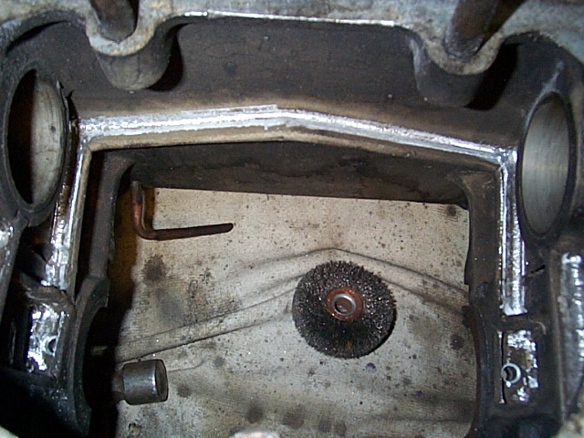
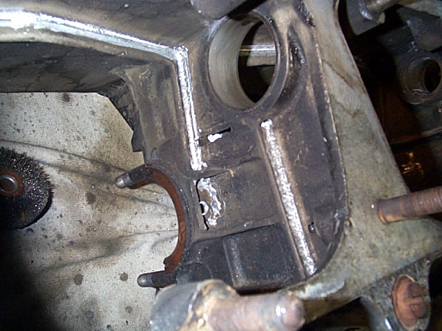
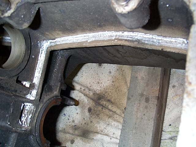
Tear Down. Bottom of Engine.

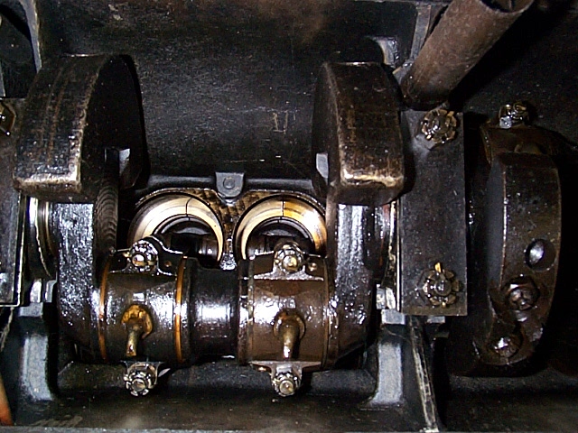
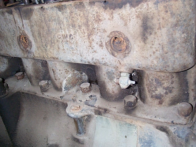

Assembly.
I took a grinder to the oil troughs. Smoothed surfaces and opened the passages into the main bearings.

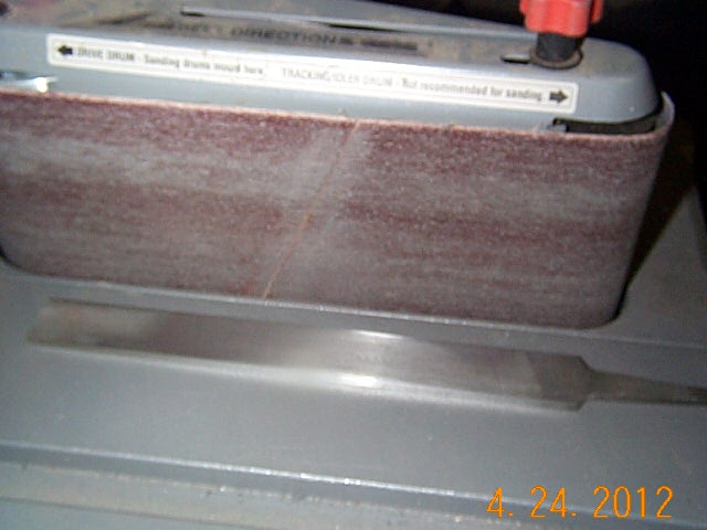
Tool I made to scrape and fit the bearings. My brother gave me this table belt sander.
I took and old flat file and made sharp edges on all 4 sides. Makes a great bearing knife.
This is the part where you need to take your time. Install the cap, spin the crank, pull the cap off and scrape the high spots.
Assembly.
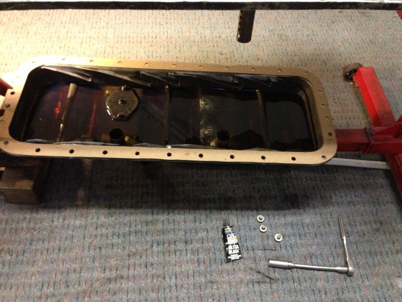
Installing Pan and Oil Gauge Float.
I used gas tank sealer to seal the cork float with. Near as I can find the ball which shows in the sight glass was painted white.
The clothes pin picture is how to hold it up while installing the pan.
Had some pin holes rusted into the dipper tray and bottom of pan. Steel torch welded those then checked with solvent for leaks.
Actually had to do this a couple of times
Pan dipper tray filled with oil before installing. BE SURE TO DO THIS!
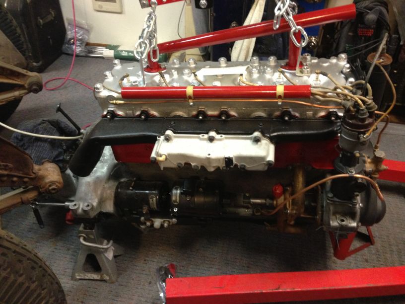
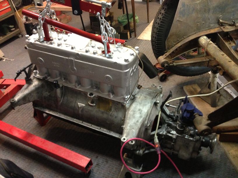
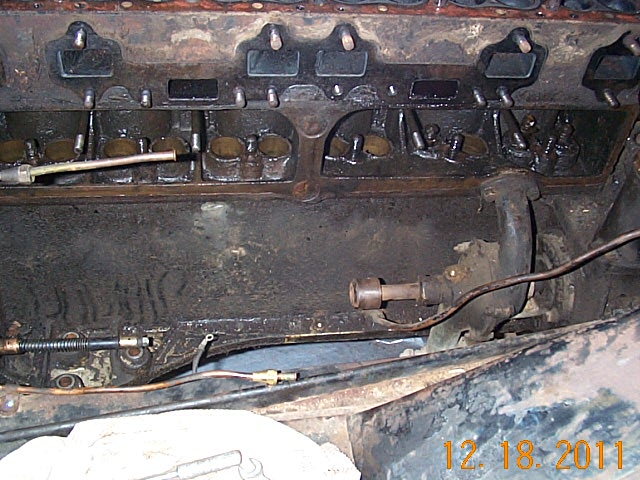
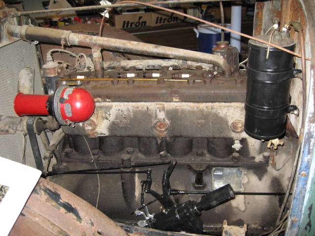
Engine on the floor ready to set into the car. Frame rails cleaned and ready to paint.

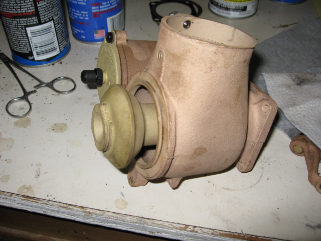
Water pump on engine with generator removed. Before and After
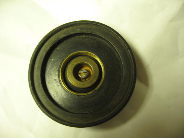
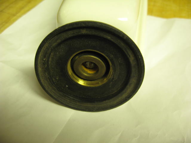
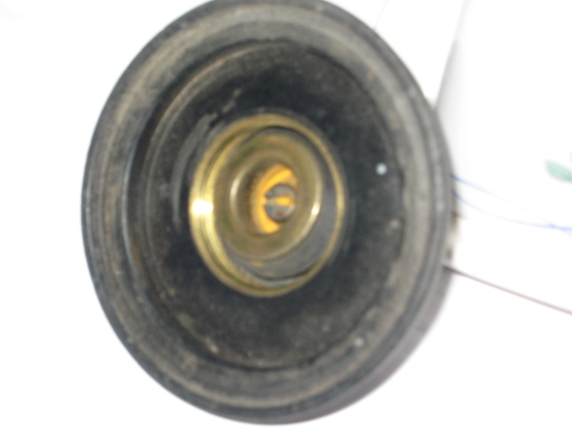
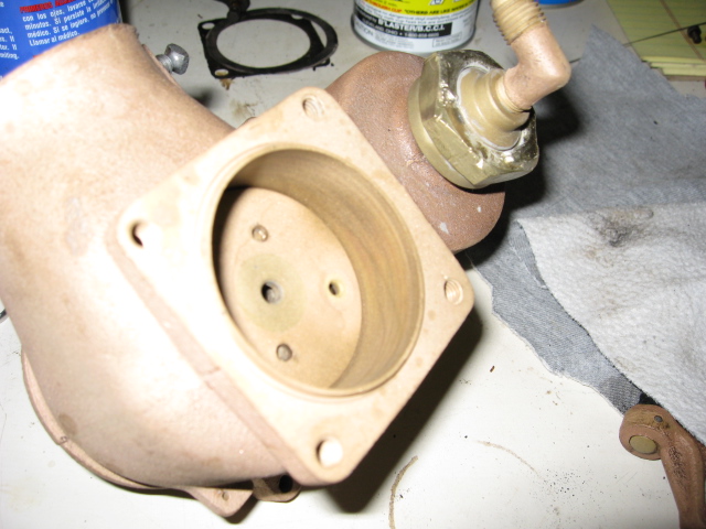
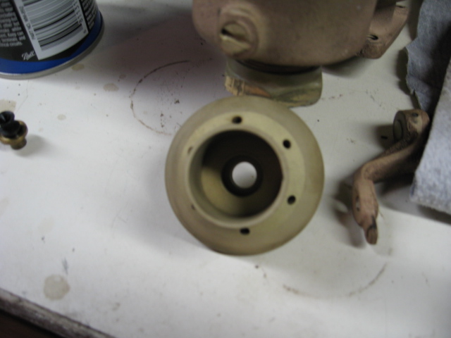
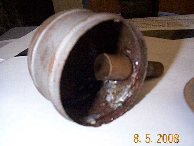
Rebuilding the Water Pump is an experience. I had 2 pumps to work with.
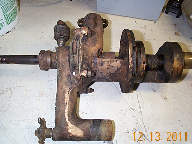
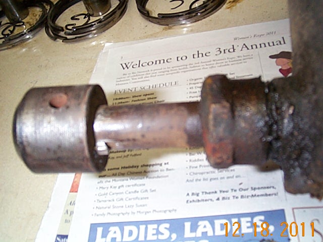

The impeller rusts to shaft even though it is brass. Take your time in pulling off the impeller.
There is a woodruff key and it's pinned to the shaft. You have to drill that out. This one had been oversized, lots of drilling.
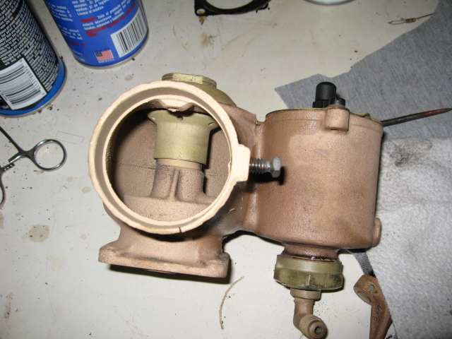
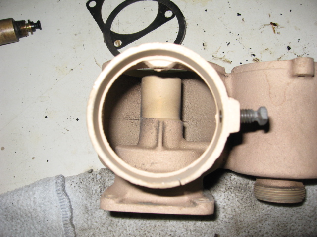
I Silver Soldered the bore and the pin holes. Bored out the impeller to fit the shaft.
Instead of drilling the impeller to shaft pin hole all the way through, I only drilled one side of the impeller.
Then I thread tapped the impeller and shaft to 1/4 inch NC and used a setscrew which bottomed to the opposite
side of the impeller bore.

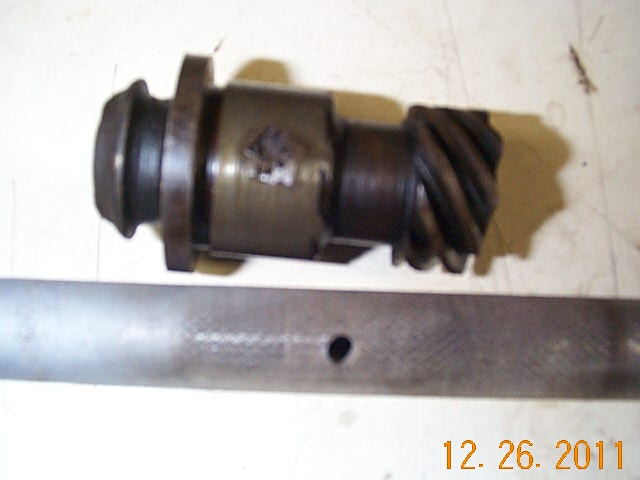
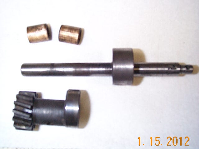
Tore down both pumps and found that one had a replaceable shaft.
The shaft was knurled and the gear assembly is pinned to the shaft.


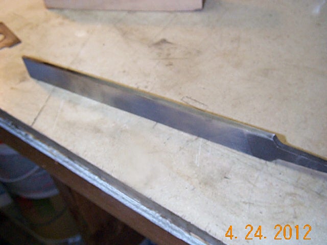
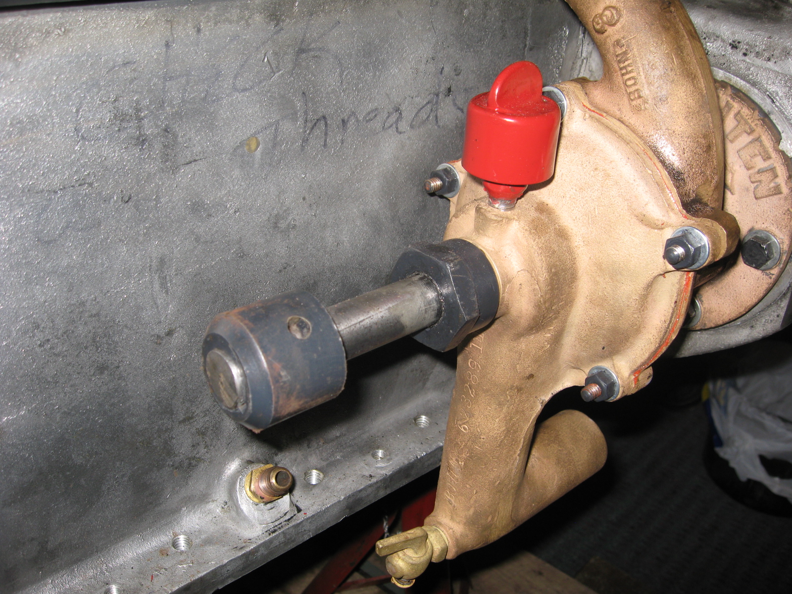
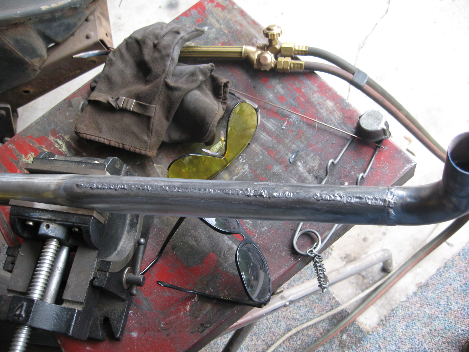
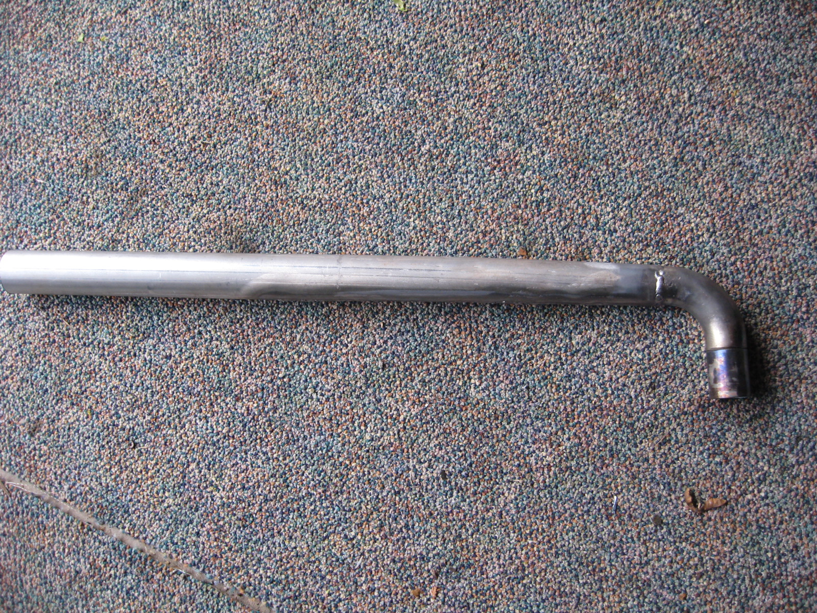
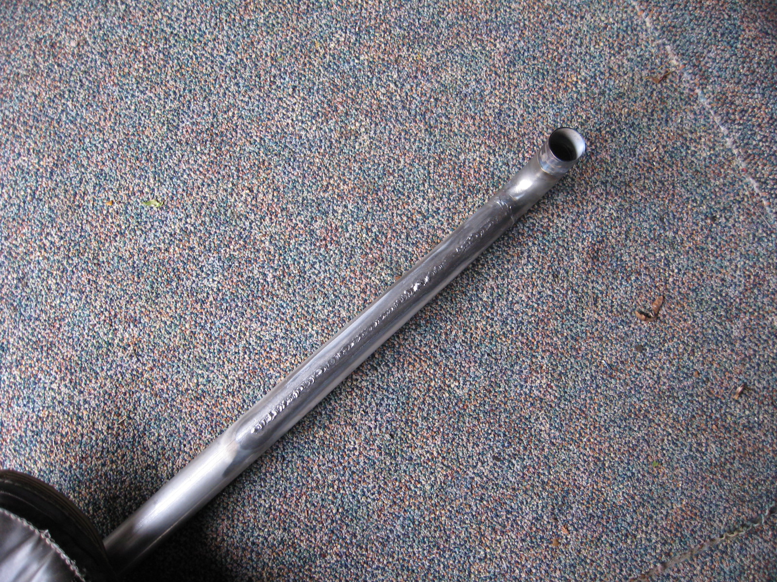
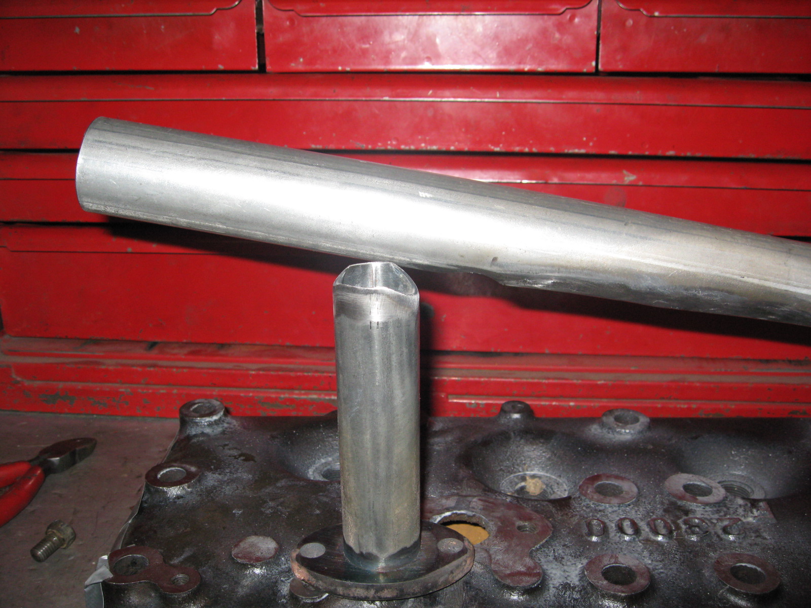
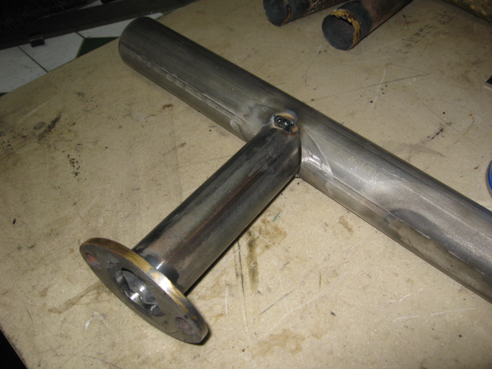
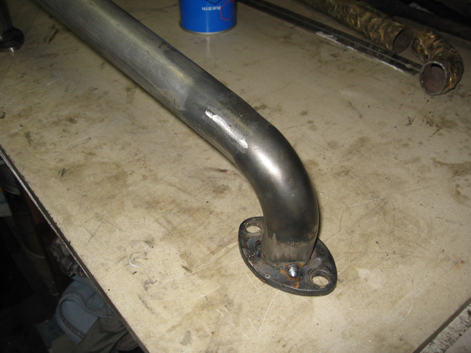
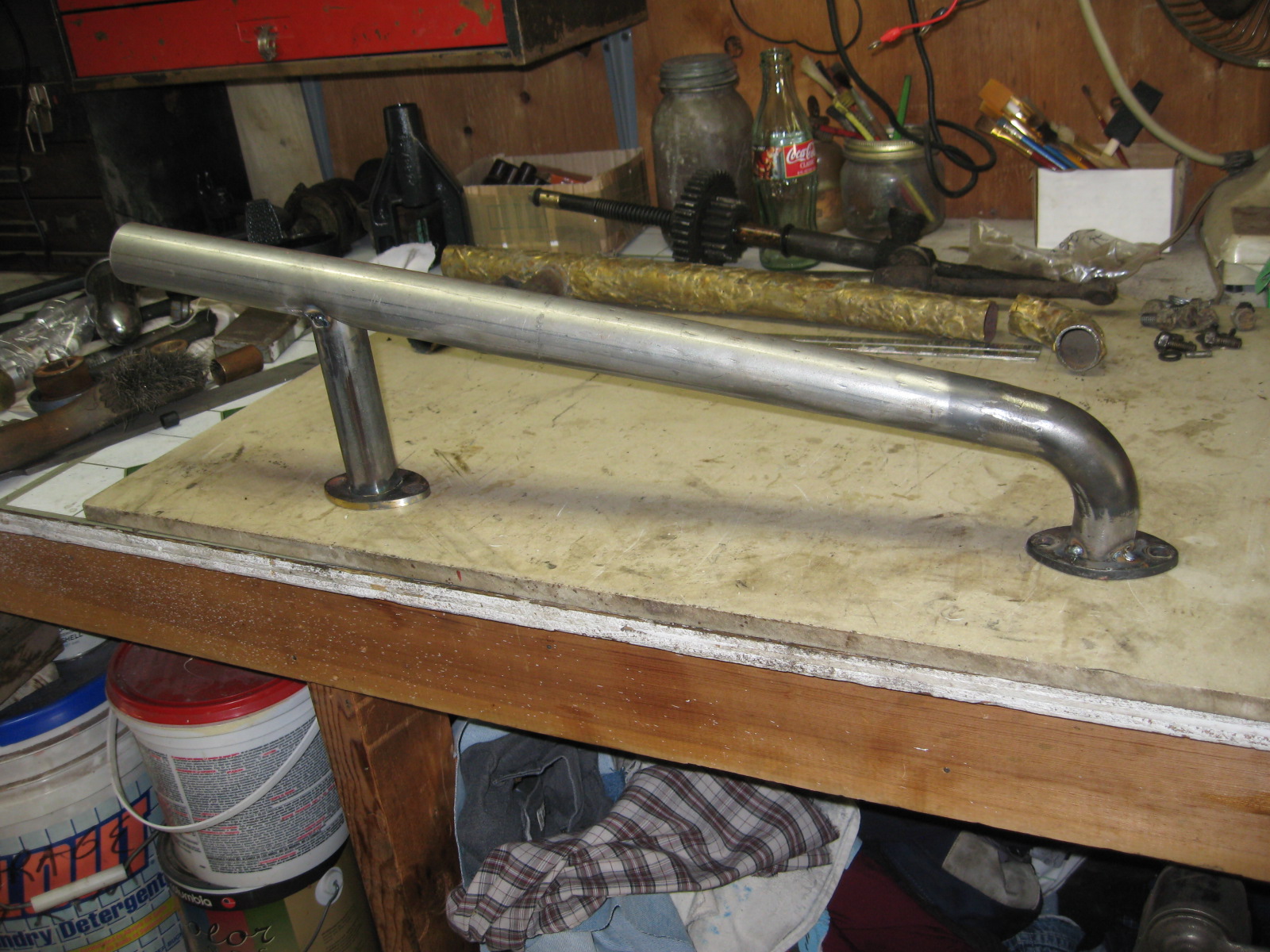
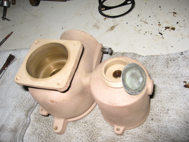
I tried to fix the old water manifold. After 3 hours of welding and having the welds crack after cooling I decided to build one.
For the elbow I used a high pressure o-ring style (button) hydraulic fitting, they are a tight bend.
For the tube I used exhaust pipe and cut a 'V' strip out of it as the originals start large at the radiator and taper down to the elbow.


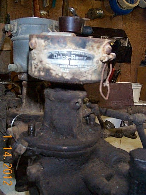
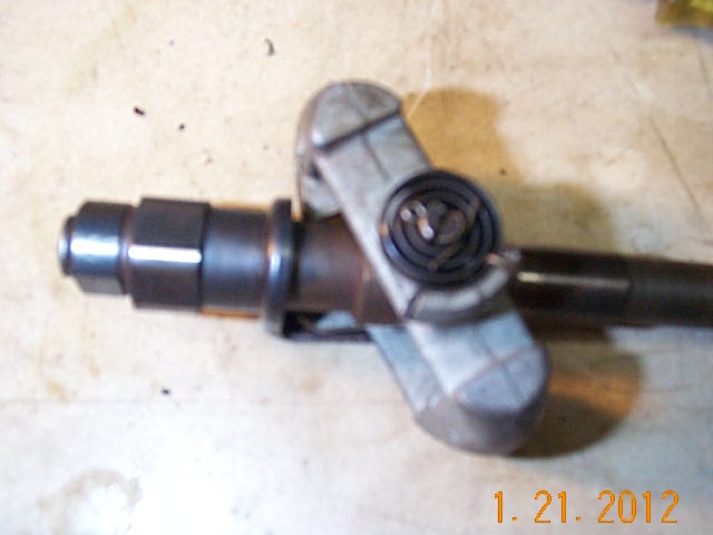
I have 3 distributors and tower assemblies. Autolite, American Bosch, Delco-Remy.
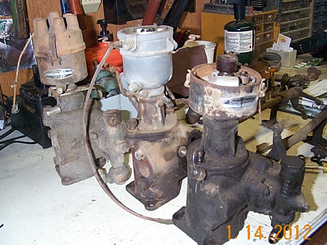
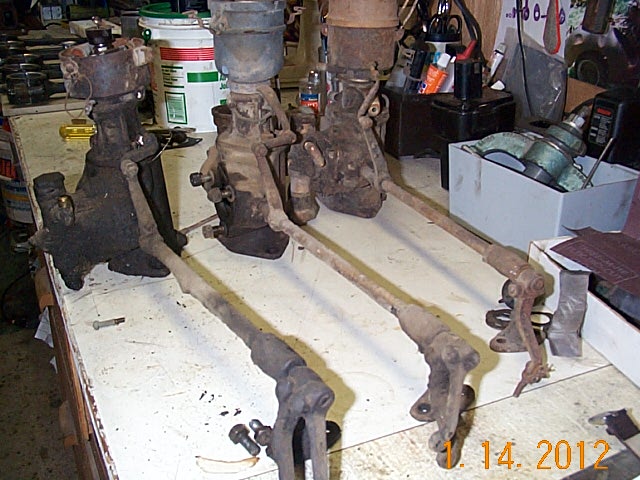
Bosch Distributor Shaft
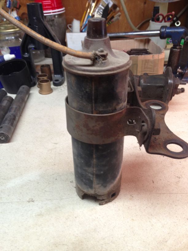
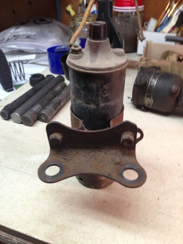
Coil

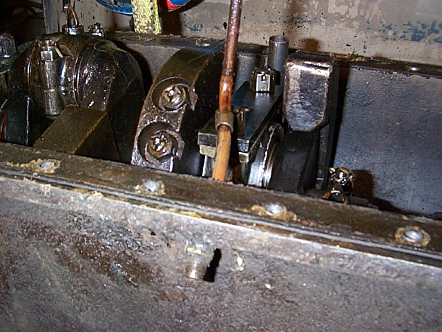
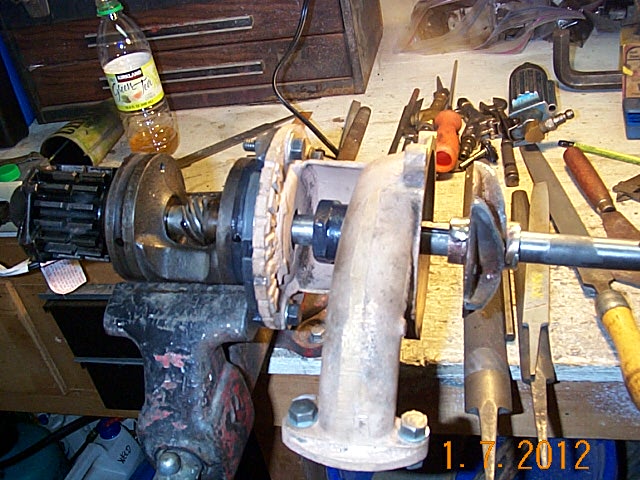
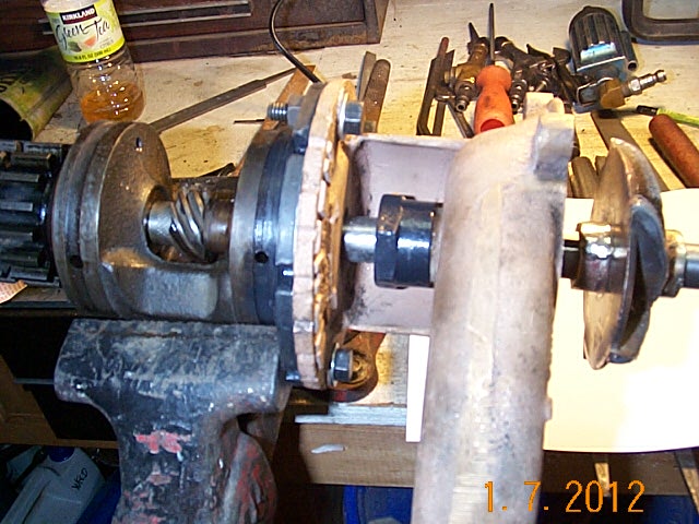
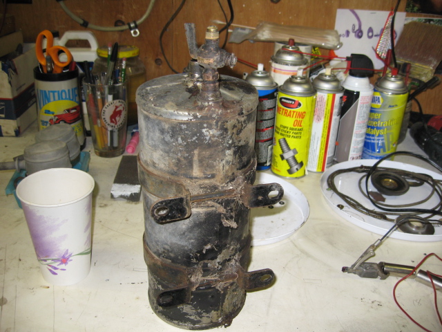
The Starter and Generator.
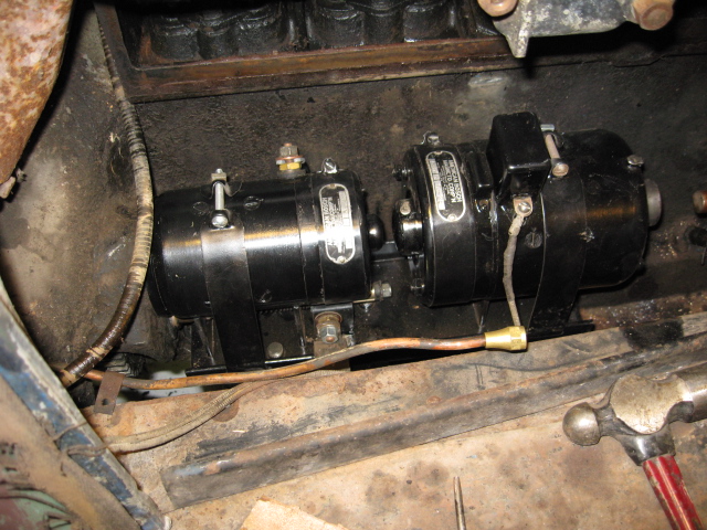

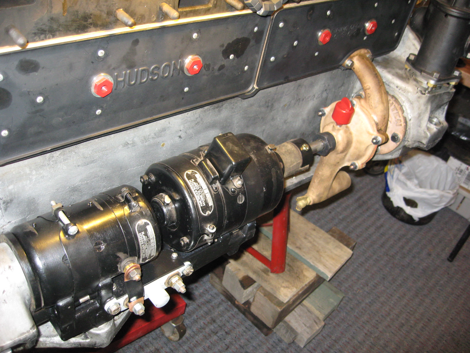


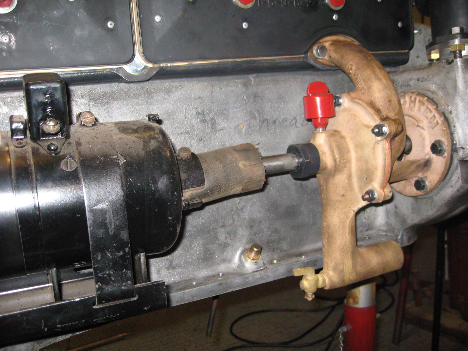
To align the generator.
In the second picture below, notice the generator is not aligned with the water pump.
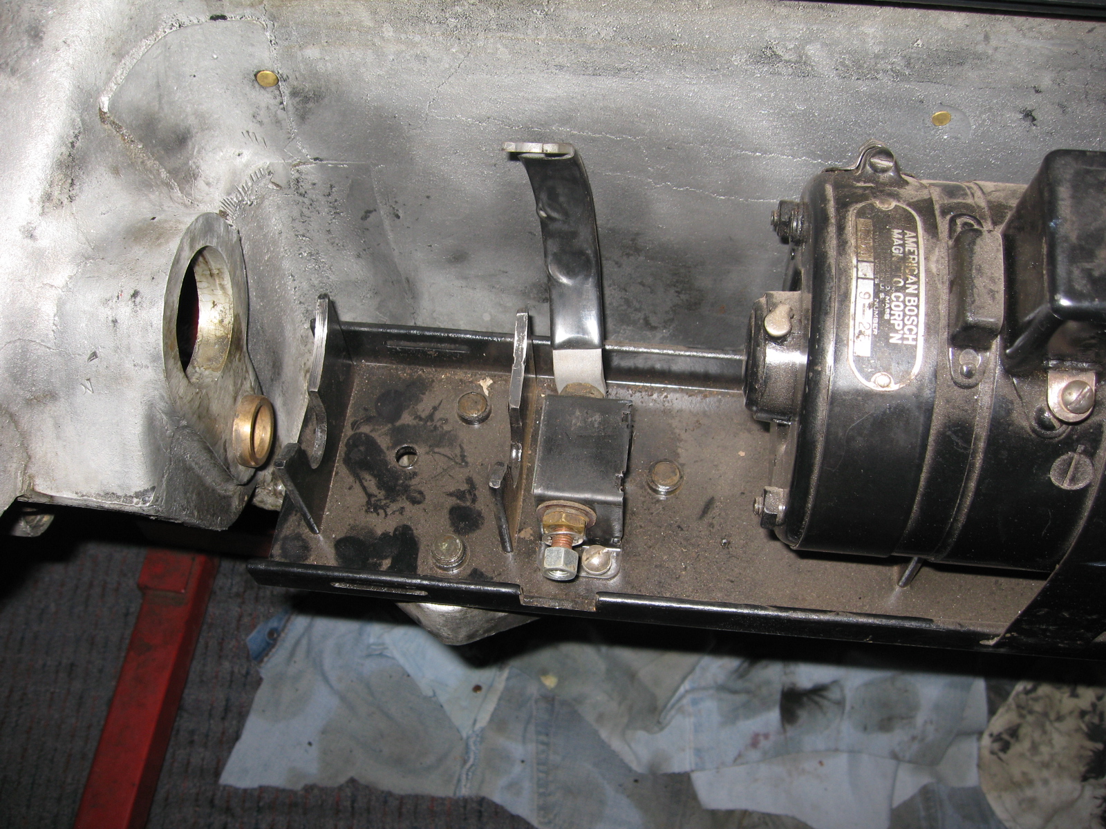
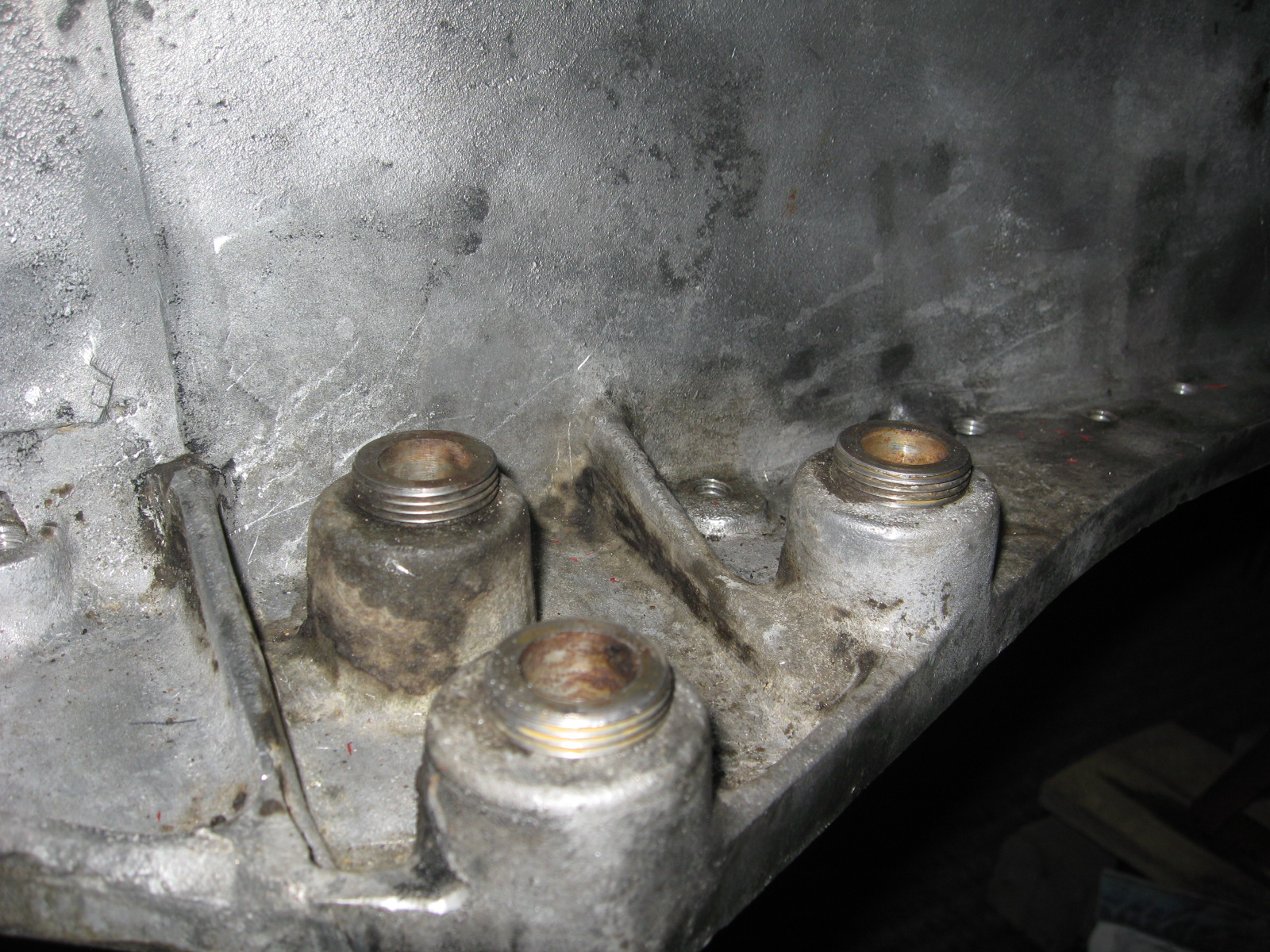
With the Generator - Starter tray removed, notice the three hollow adjustor sleeves.
Screw these up or down until you get a level reading with a straight edge across the water pump and generator drive couplings, sixth picture.
Finally, measure from the bottom of the pan rail to the top of each adjustor to make all same height.
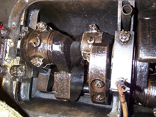
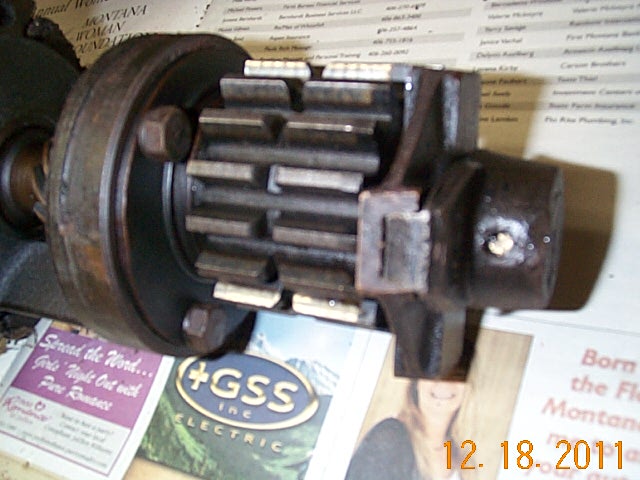
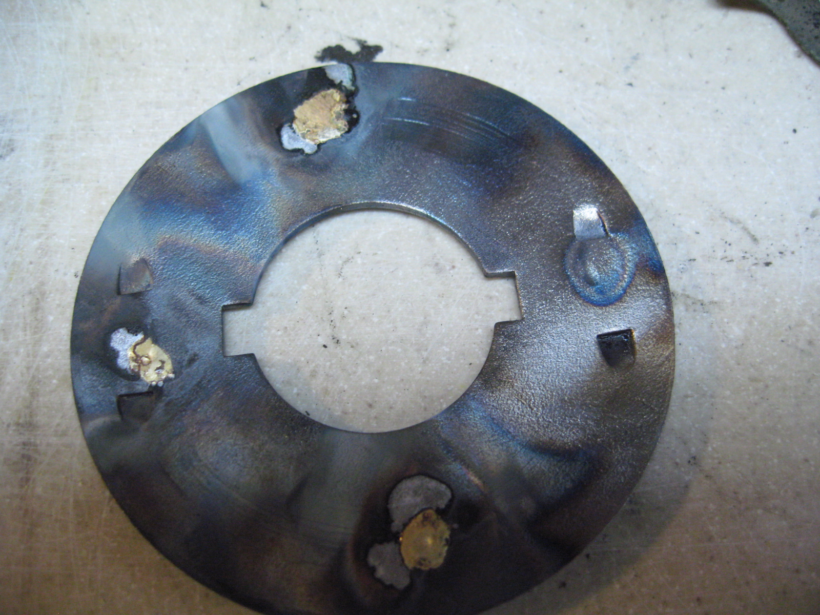
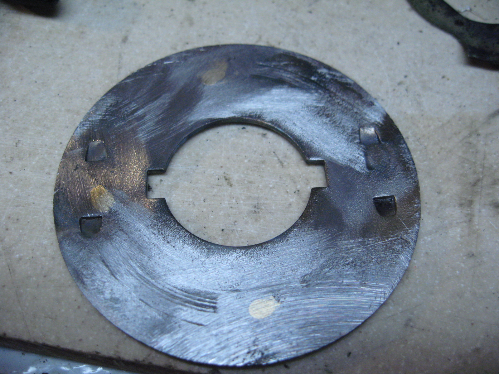
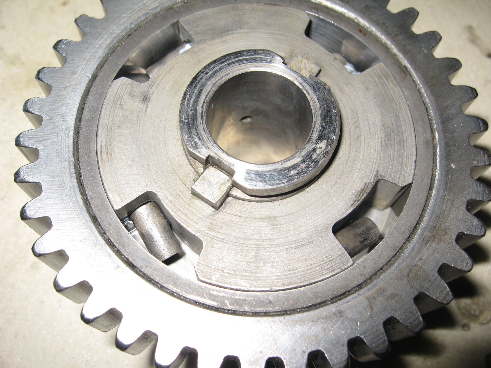
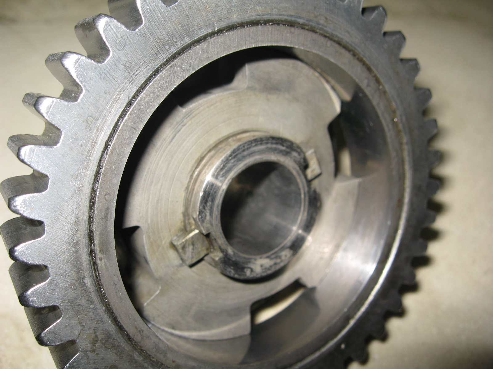
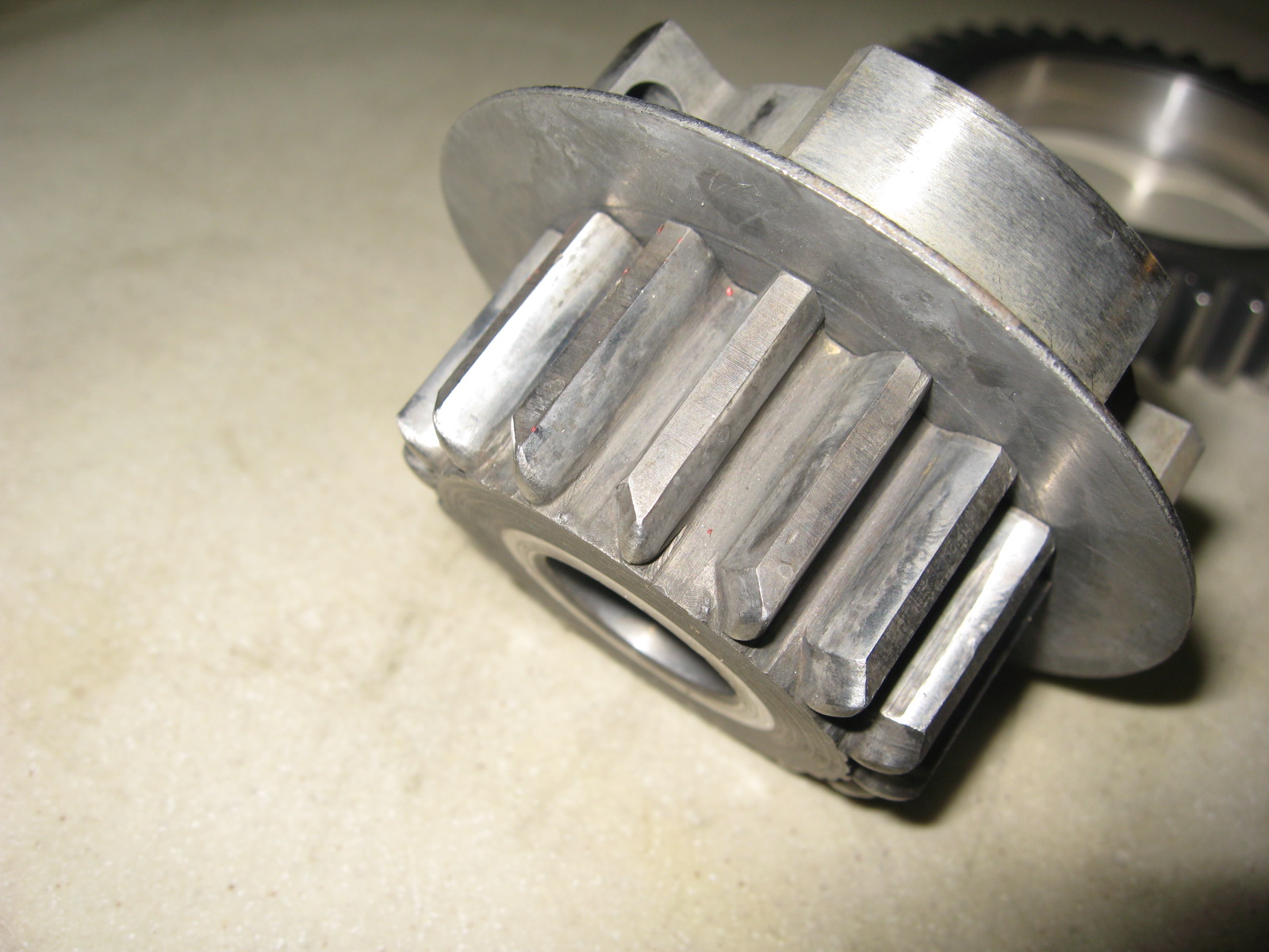
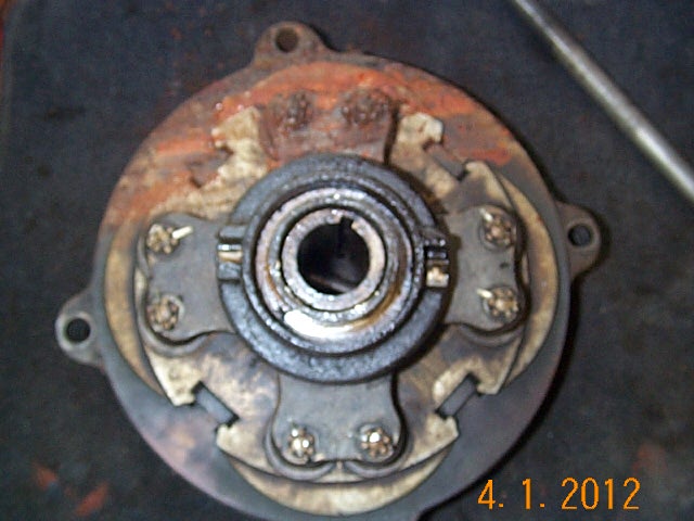
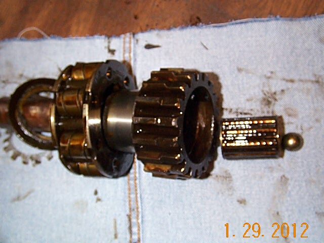
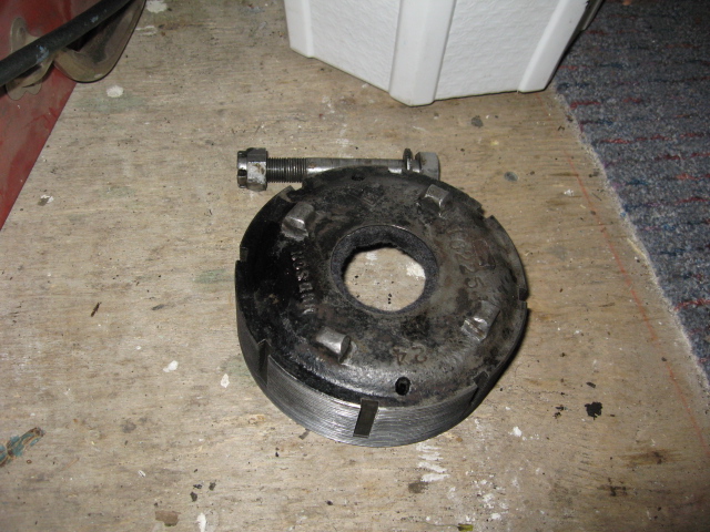
Starter Gear, Clutch Rebuild.
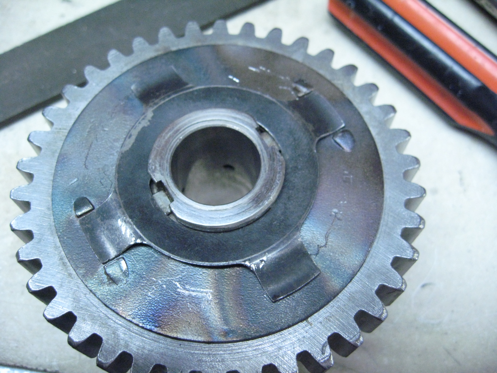
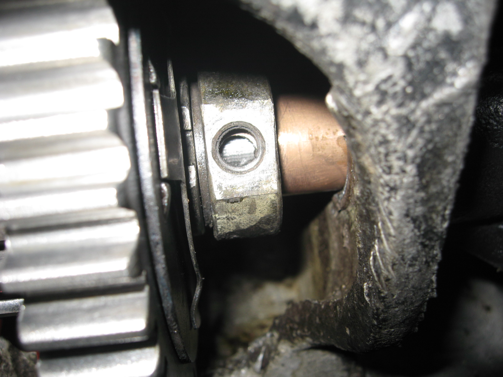
To remove the lock plate, rotate the plate past the the raised taps until the flats in the lock plate line up with the flats in the clutch gear.
Opposite of the picture below, (this is showing assembly).
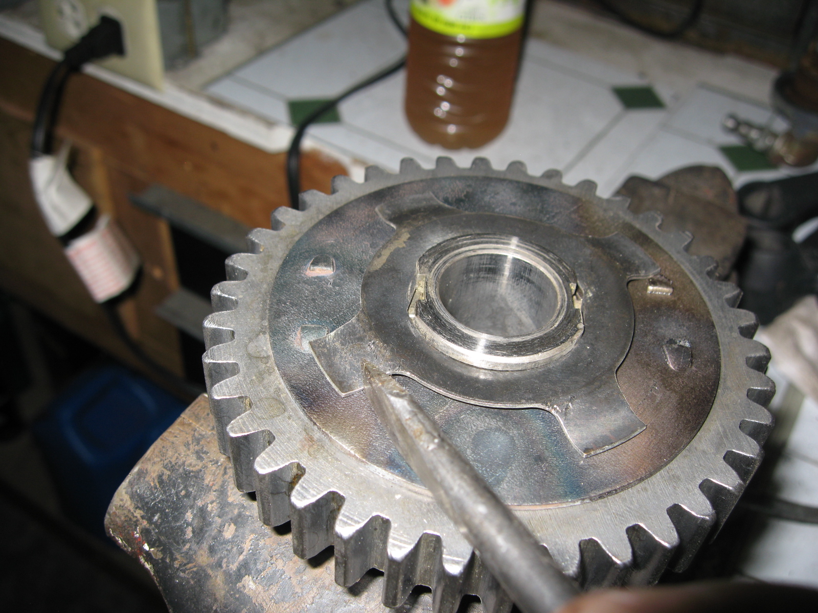
After the flats are aligned push the lock plate sideways and pry the ring out of the groove opposite the side you drove on.
Insert a screw driver under the ring (top of picture below) so it is out of the lock groove then drive back (bottom of picture below) to release the ring.

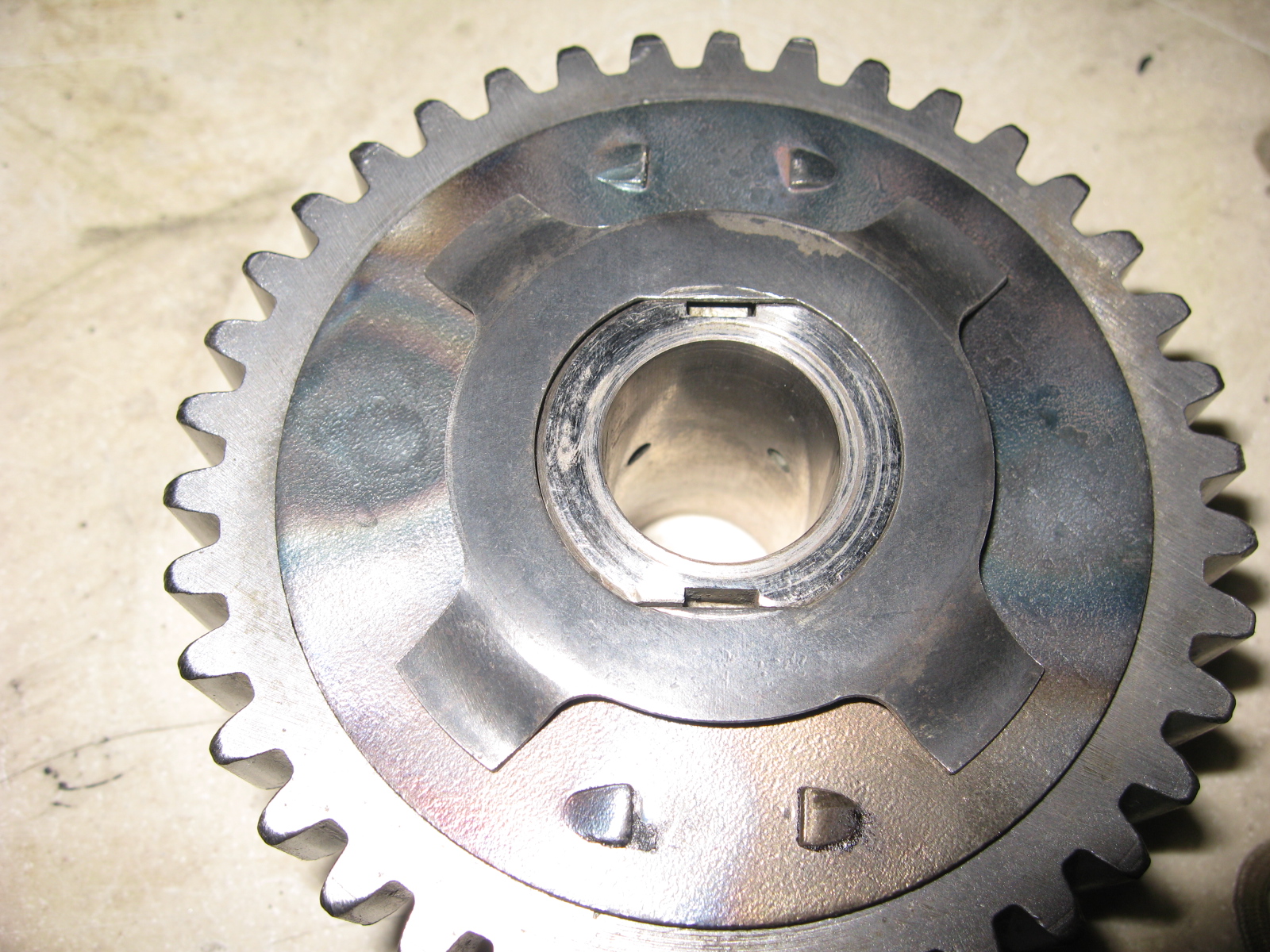

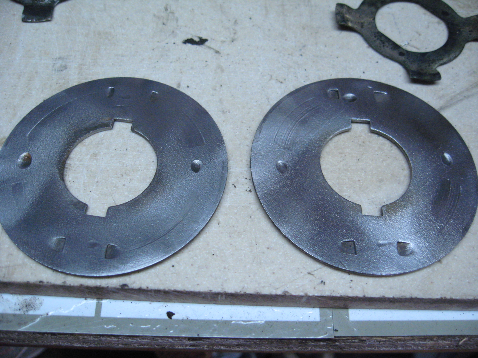
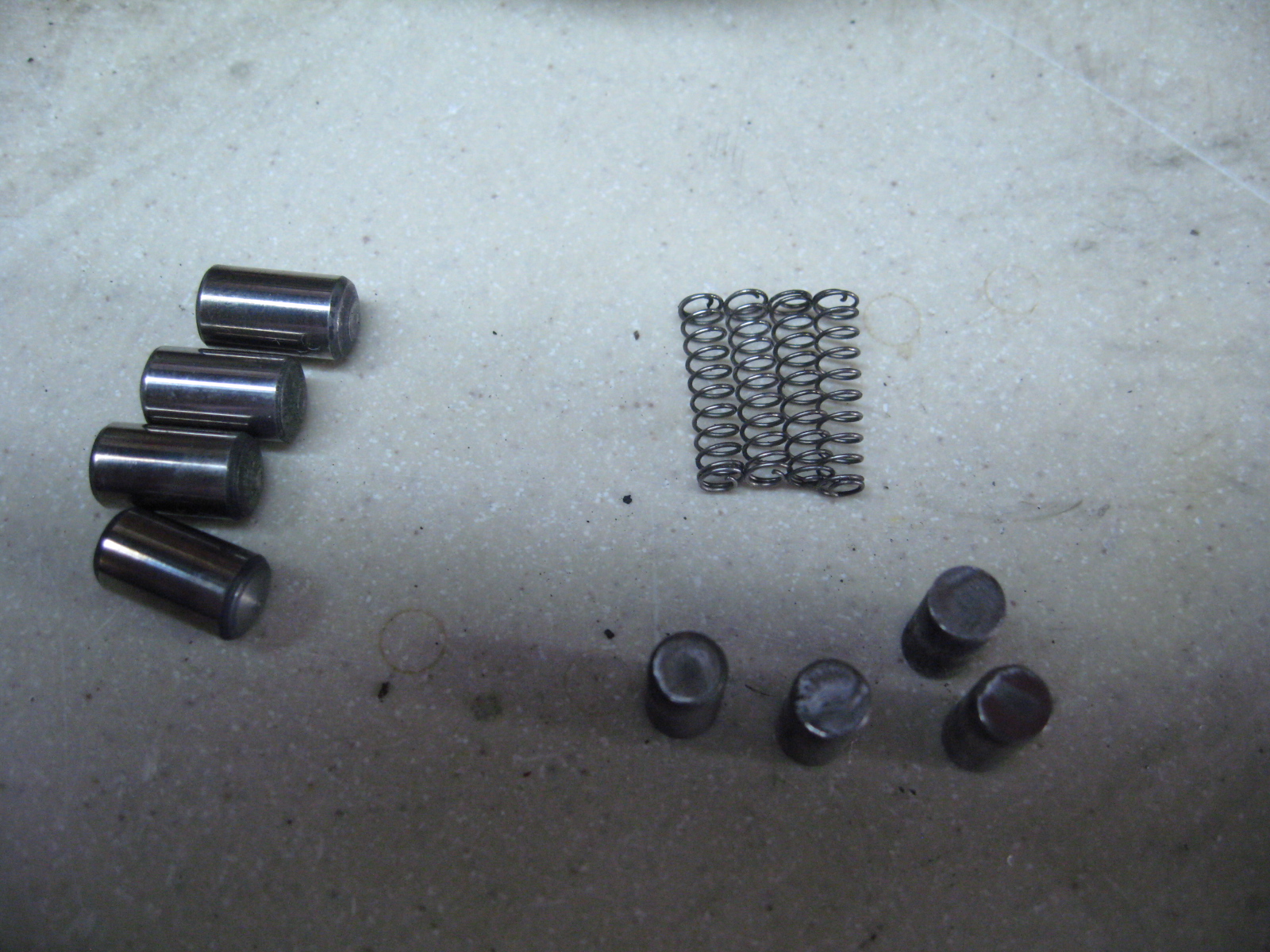
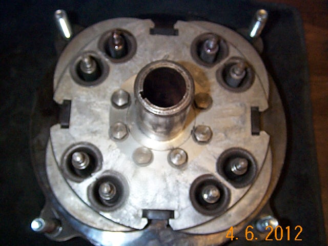
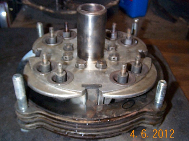
Now the plate can be removed to reveal the rollers, spring caps, and springs. I had an extra clutch and choose the best parts of the 2.
Both plates had indents from the rollers wearing on the plate so I filled one with brass and ground flat.
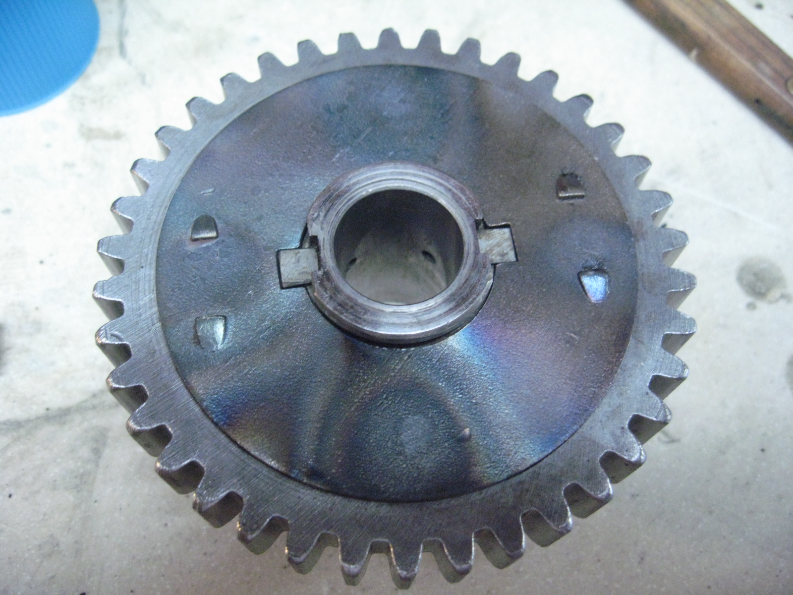

Finally, check the wear on the clutch rollers and where the gear runs on the gear/shaft.
Also compare the spring lengths. Lubricate the spring caps and rollers when assembling.


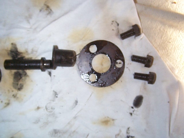
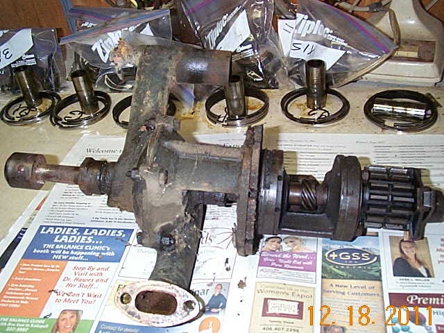
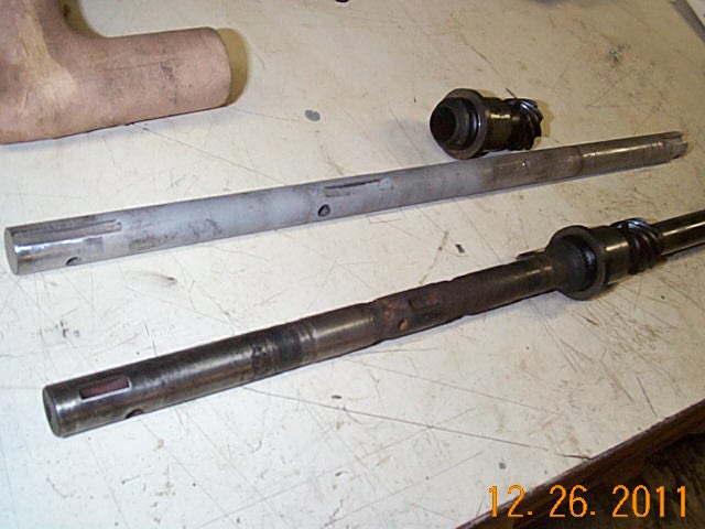
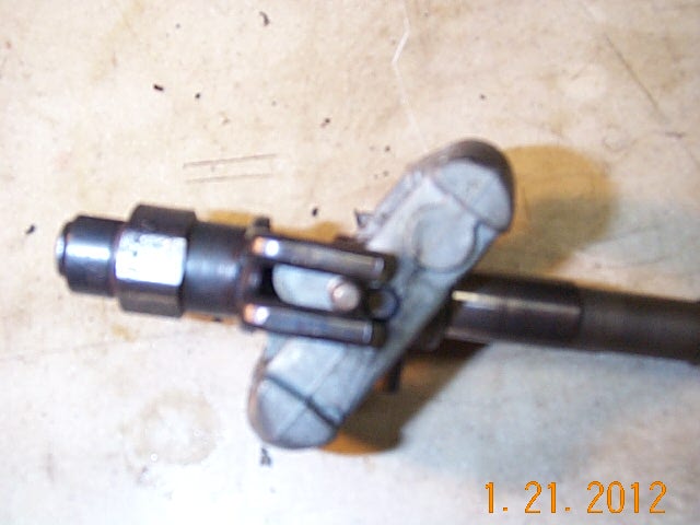
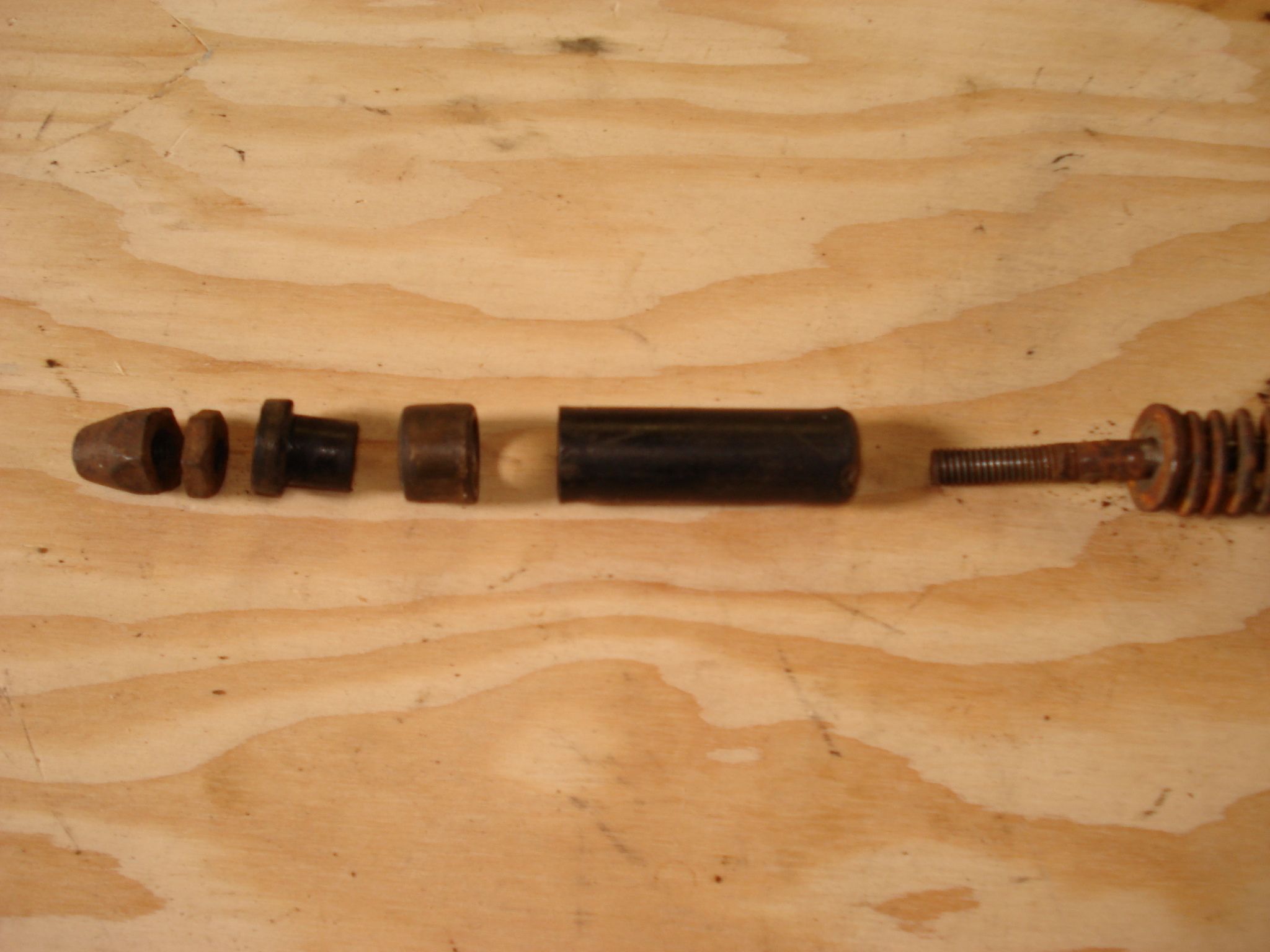
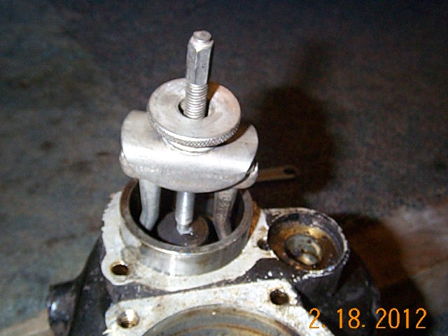
Starter shaft.
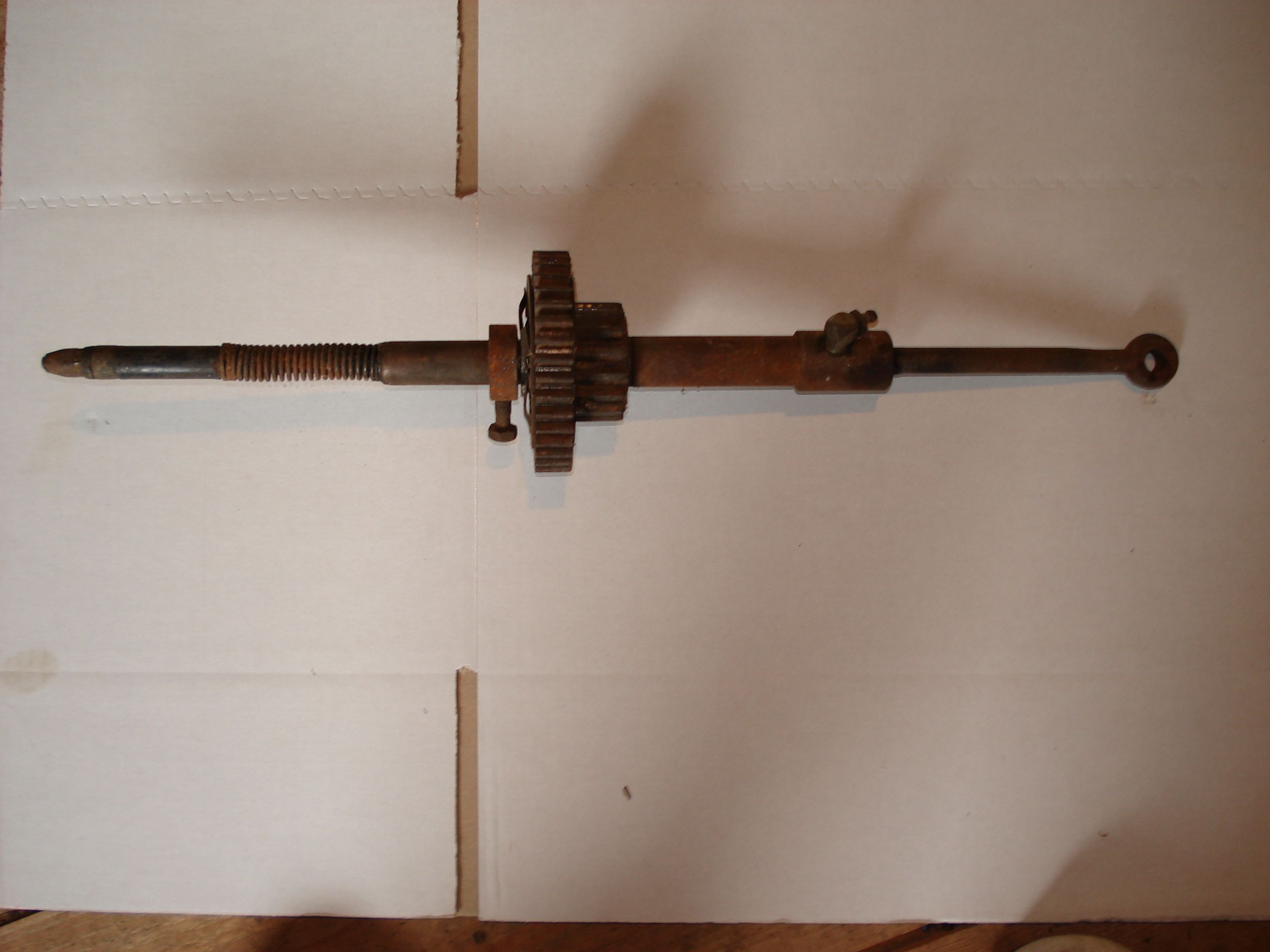
Sleeve assembly apart. 4th item from left is copper sleeve which slides trough contacts to engage starter.
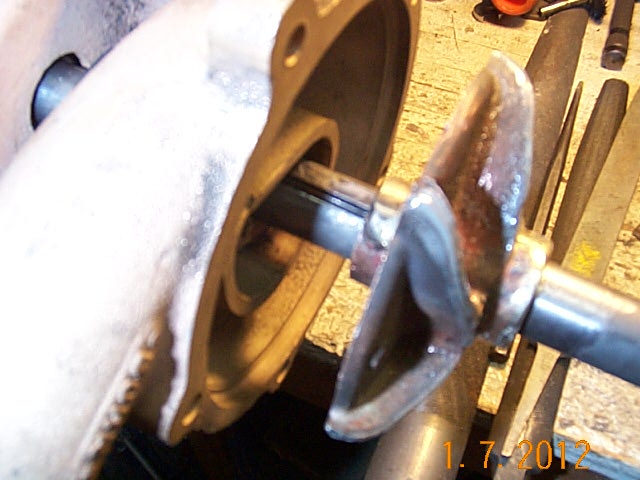
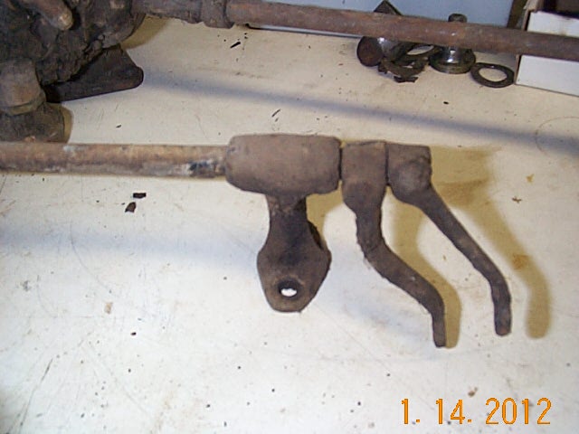
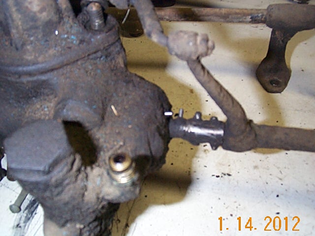
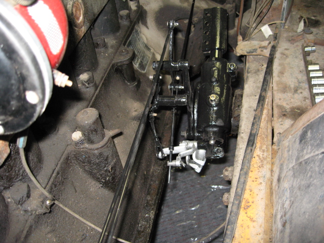
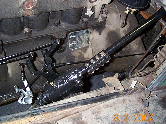
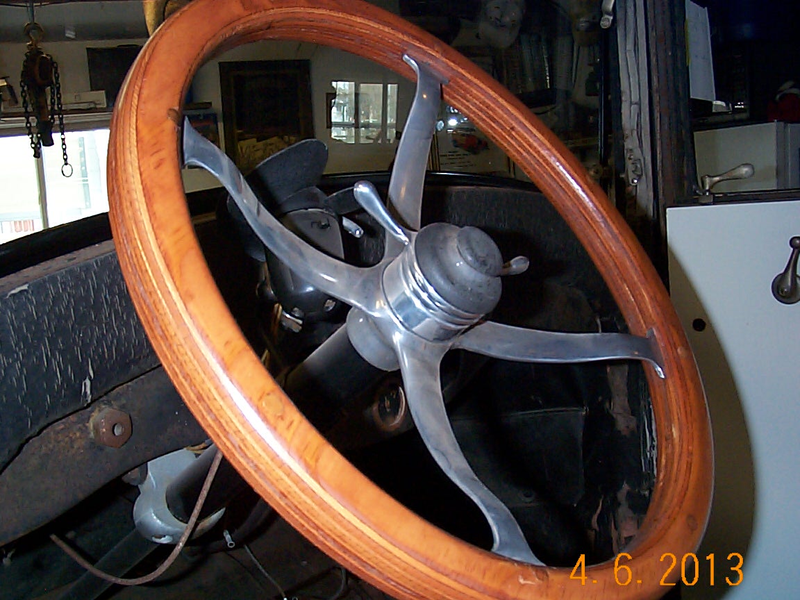
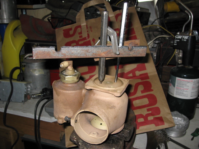
Rebuilding the steering box.
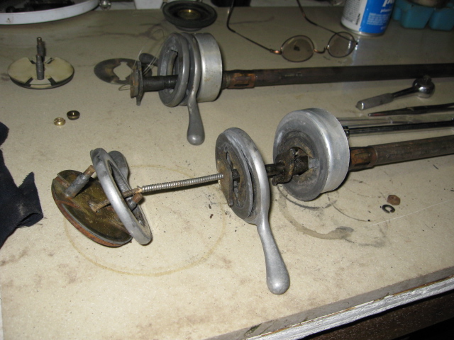
Trying to pick the best of available parts.
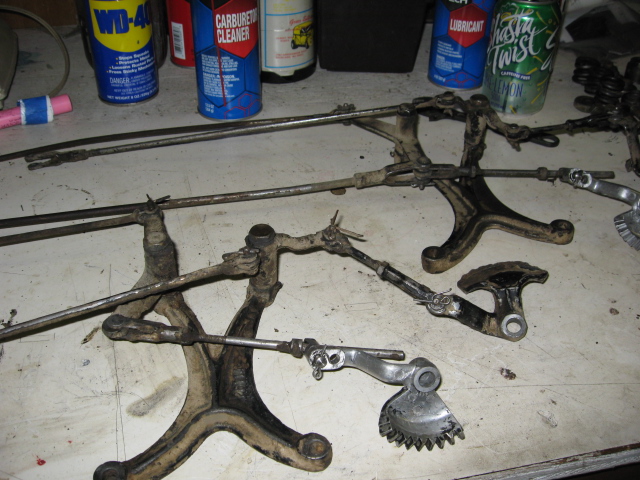
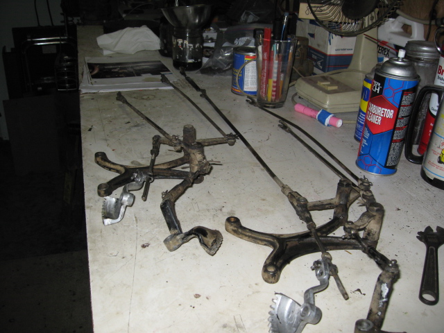
Installed and working like a champ.

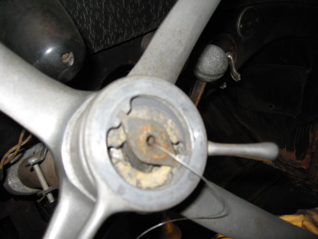
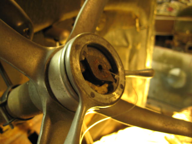
I mocked up a steering wheel until I get the original rebuilt this winter.
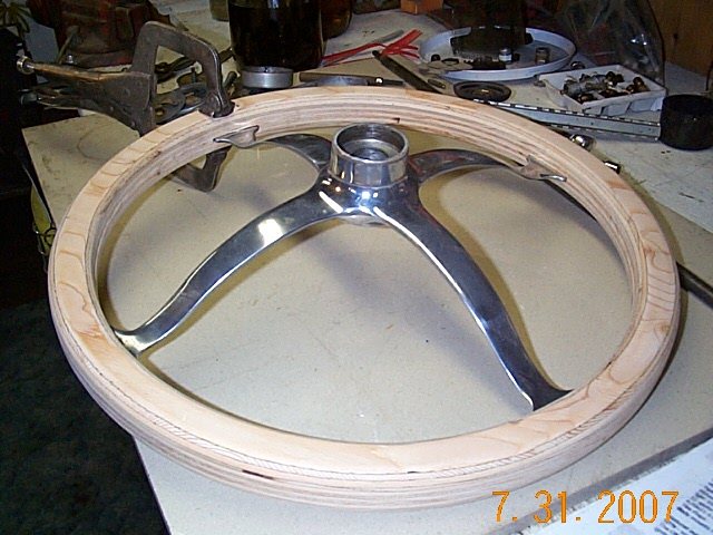

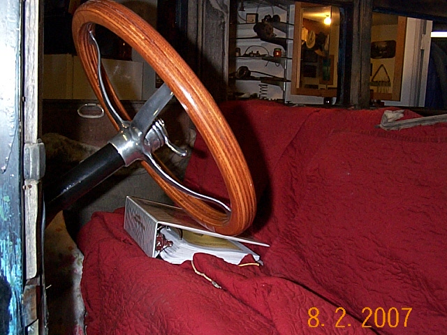
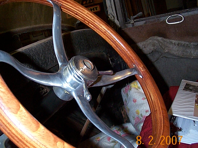
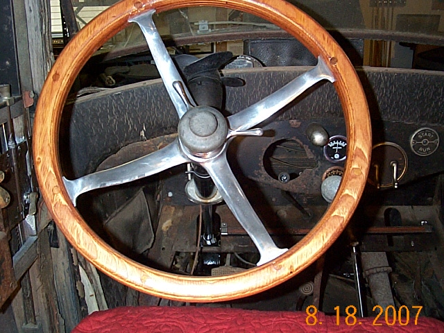
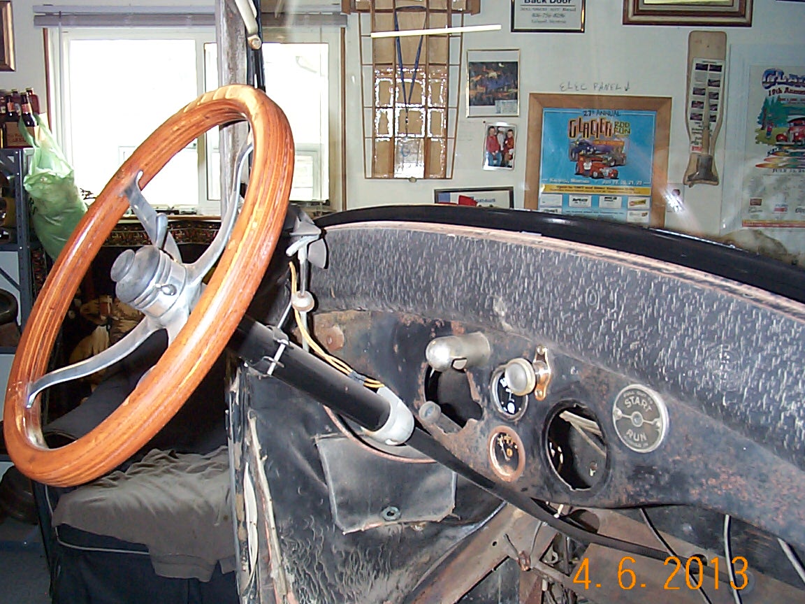

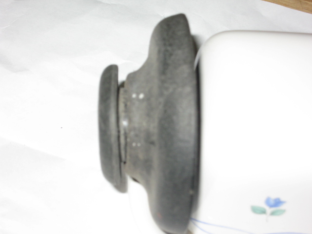
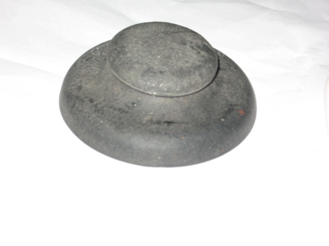
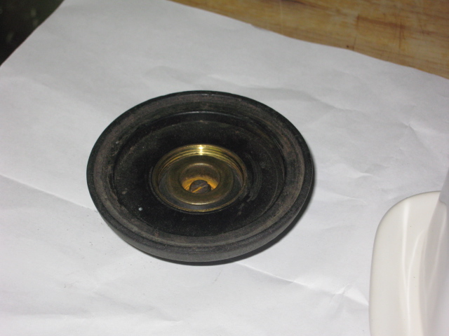
1925 Hudson Horn Button.
Clutch parts.
The arrow in the first picture has a reason but I rebuilt this 2 years before I posted these pictures on the site and I cannot remember.
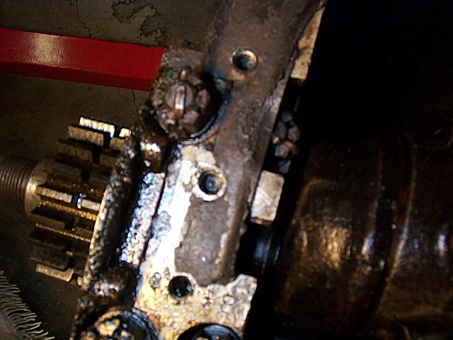
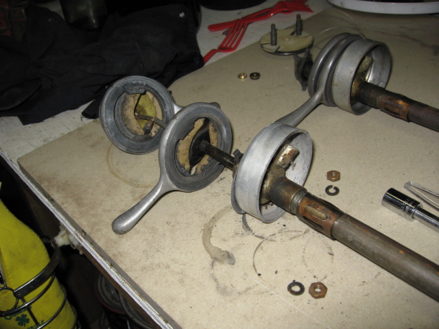
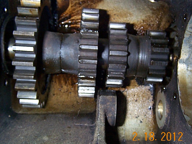
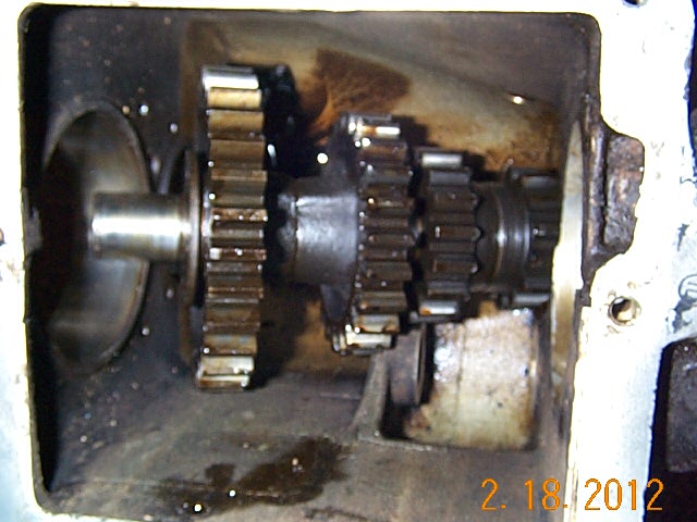
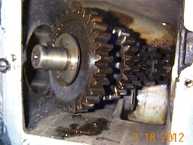
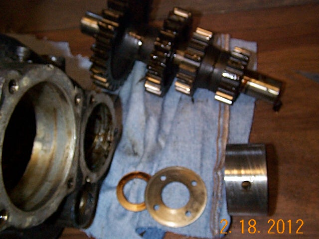
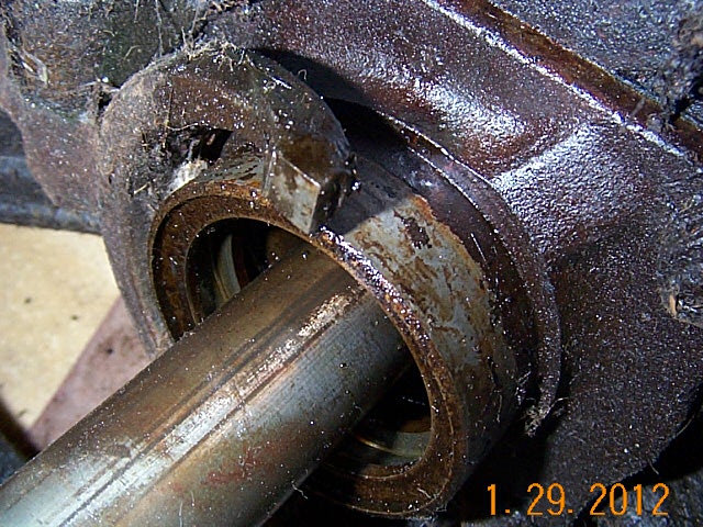
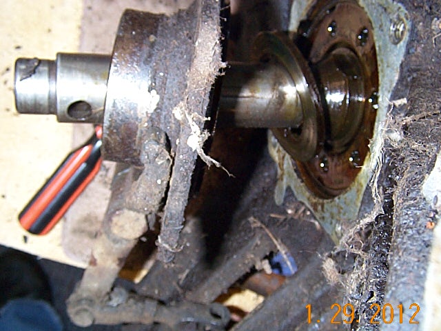
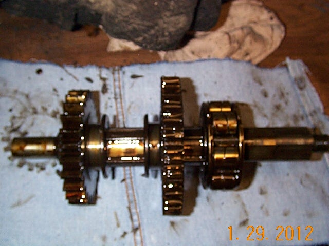
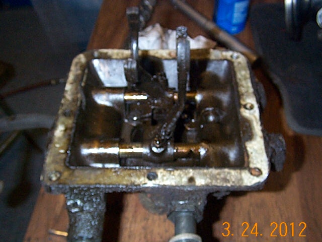
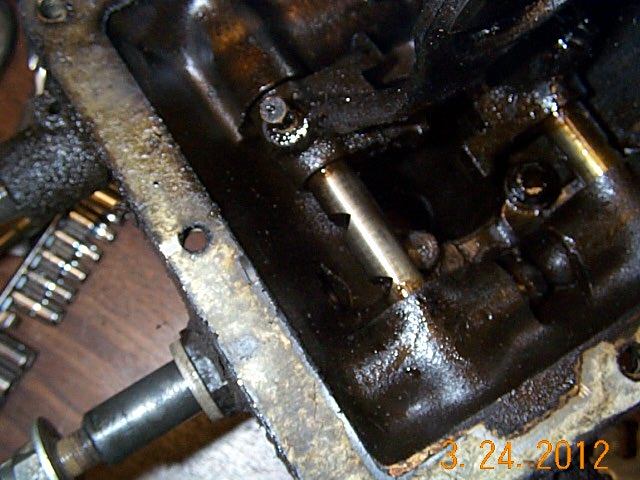
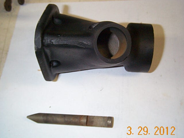
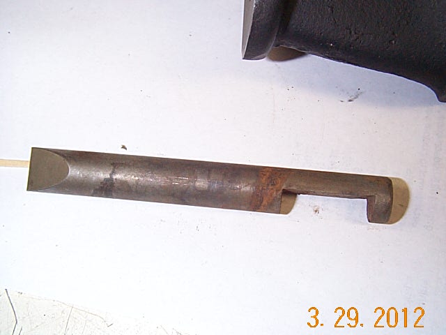
Tore down both transmissions. Able to make one good one from the both.
![]()
![]()


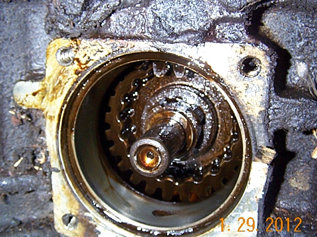
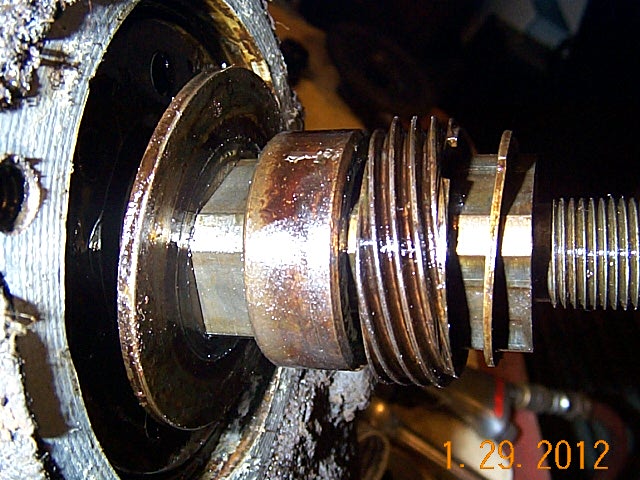
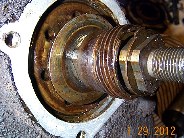
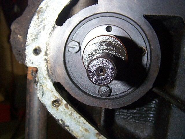
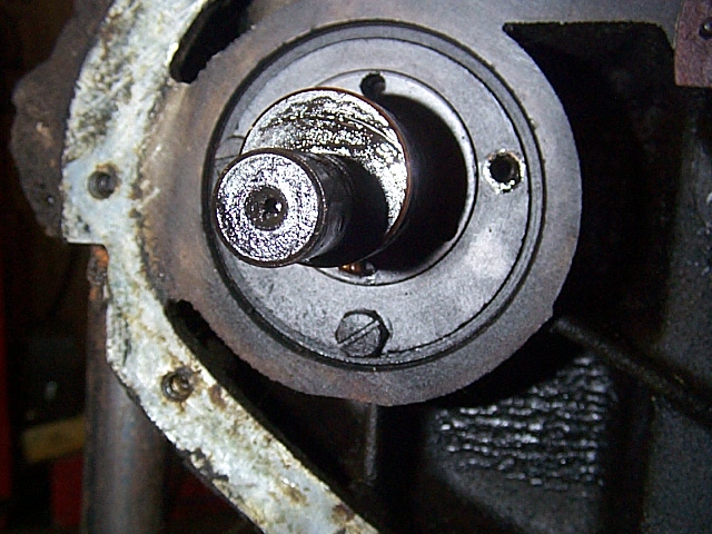
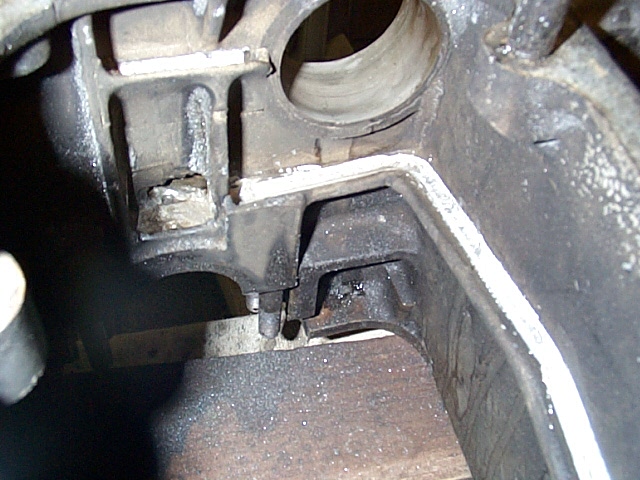
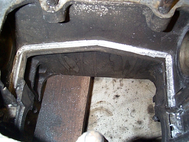
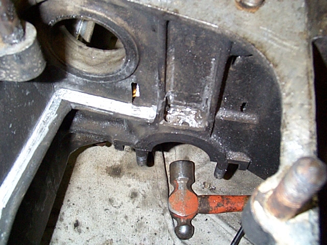
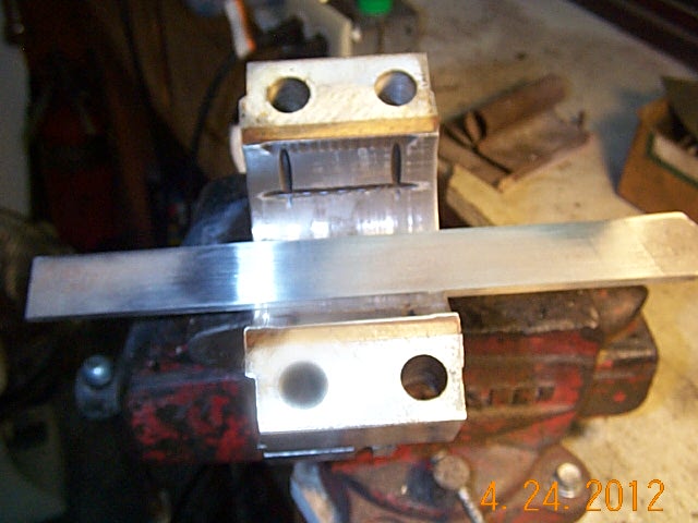
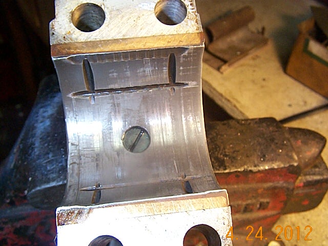
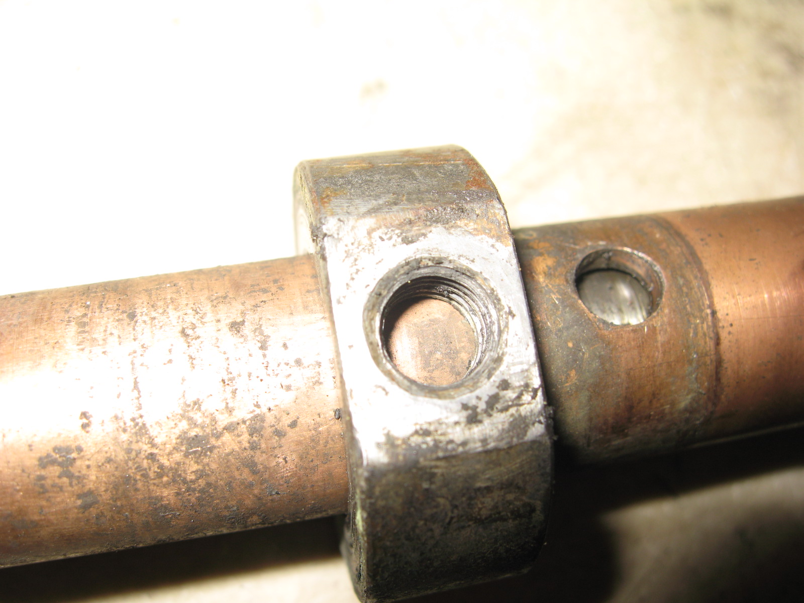
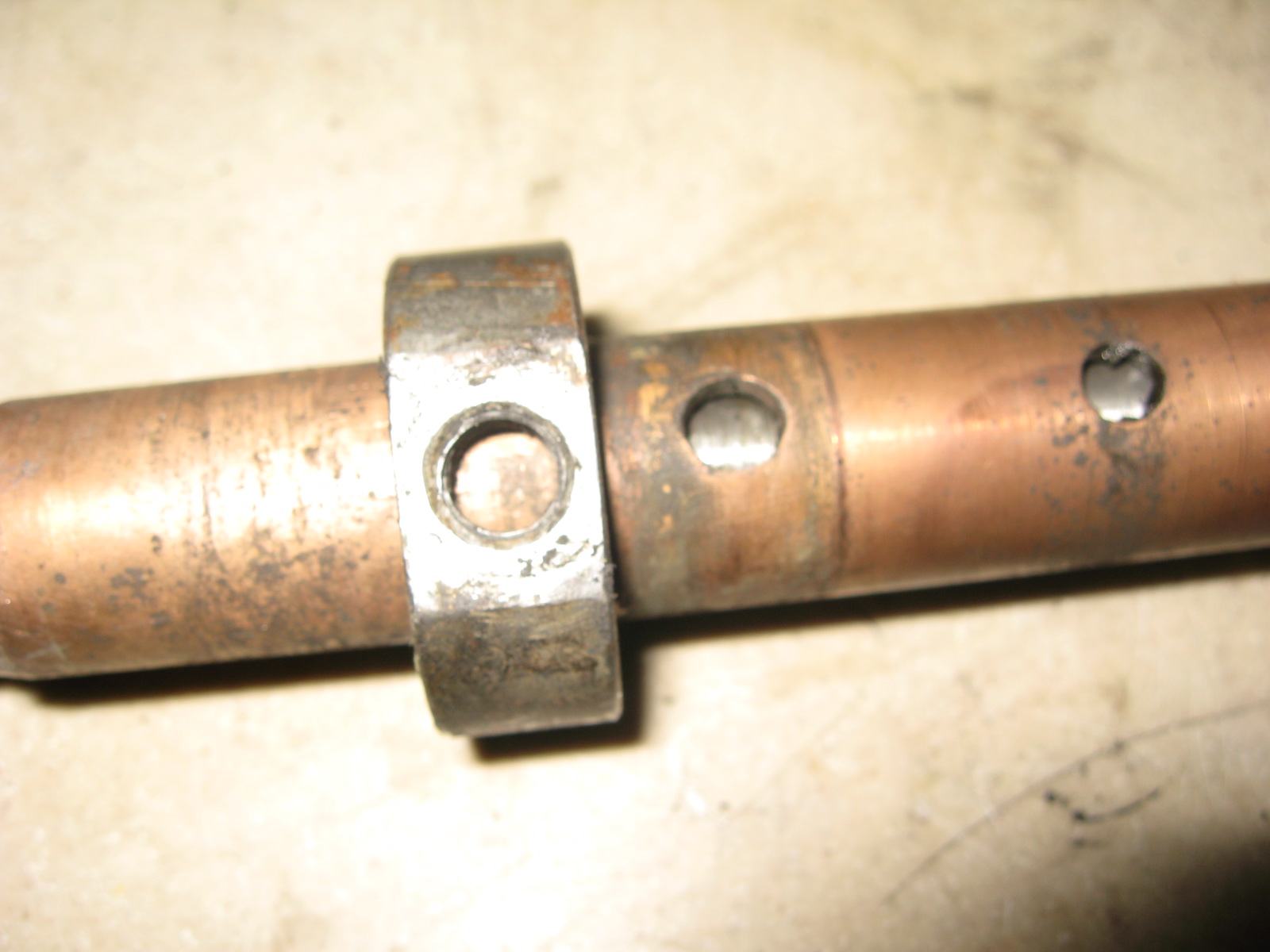
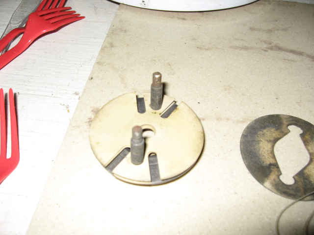
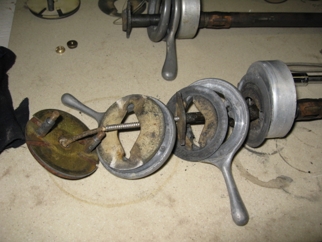
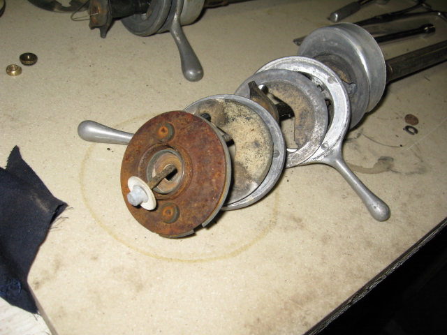
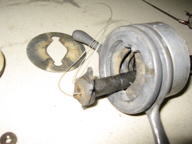
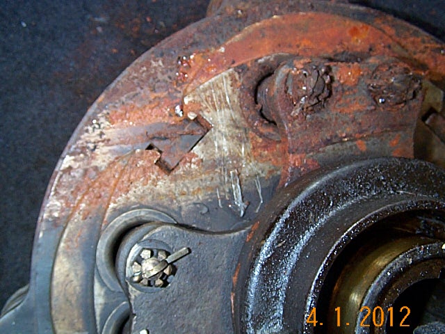
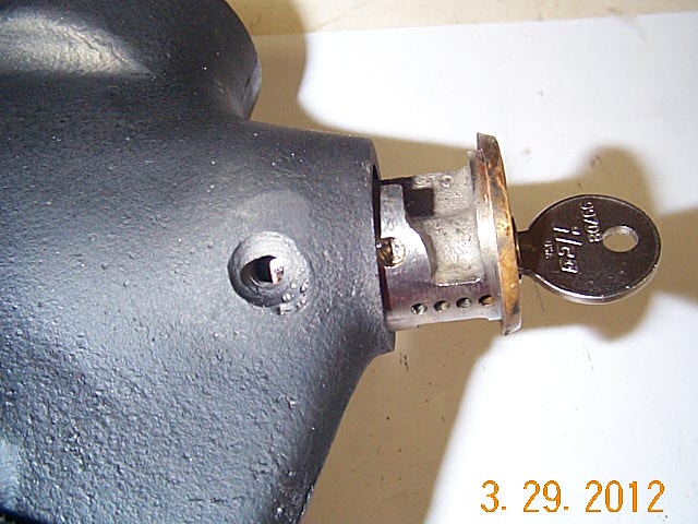
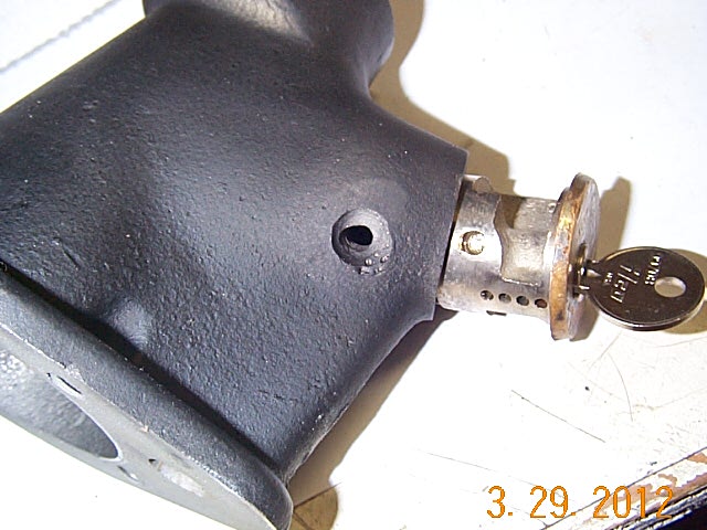
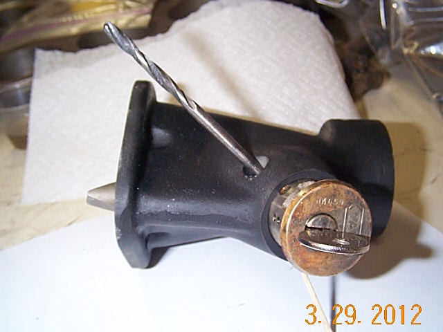
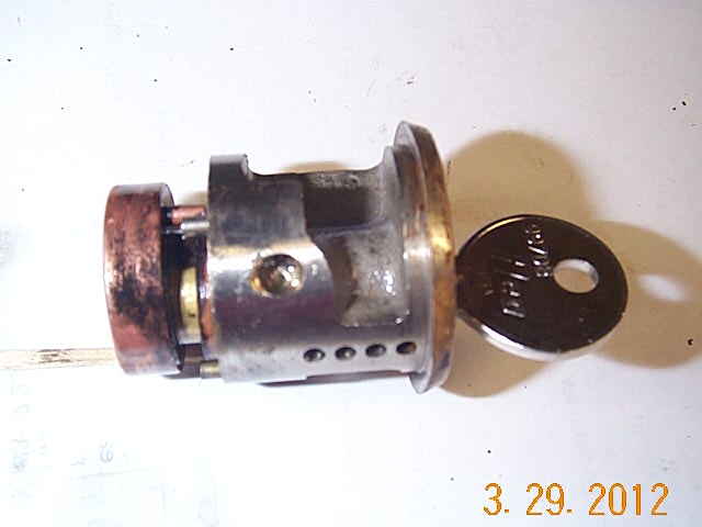
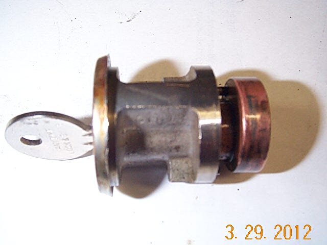
Shift tower. How to remove the key assembly.


There is a pin in the tower which indexes to a hole in the lock assembly. It is spot welded. See third picture this row.
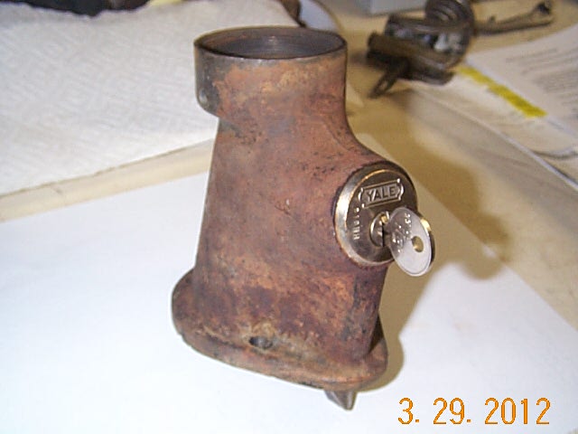
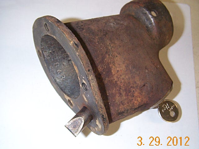
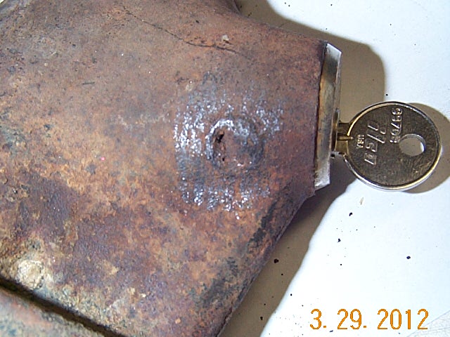

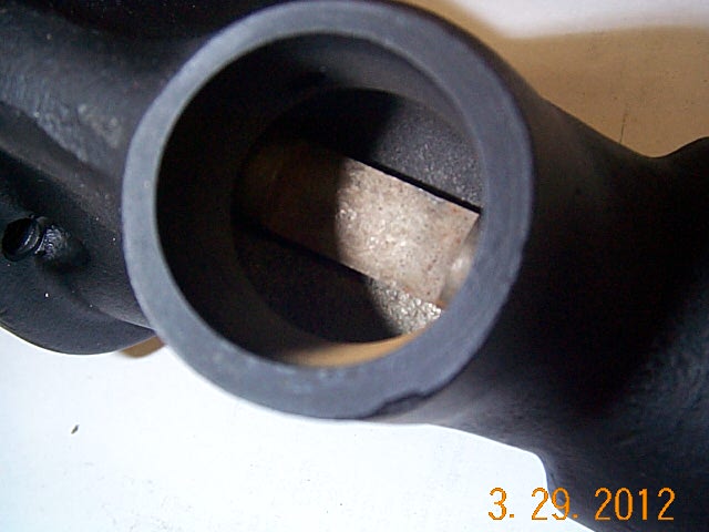
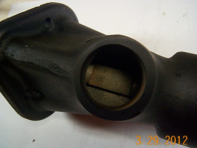
I ground the weld down until I could see the outline of the pin. Drilled and tapped the pin to pull it out.
See next to last picture of this row to see hole the pin fits in.

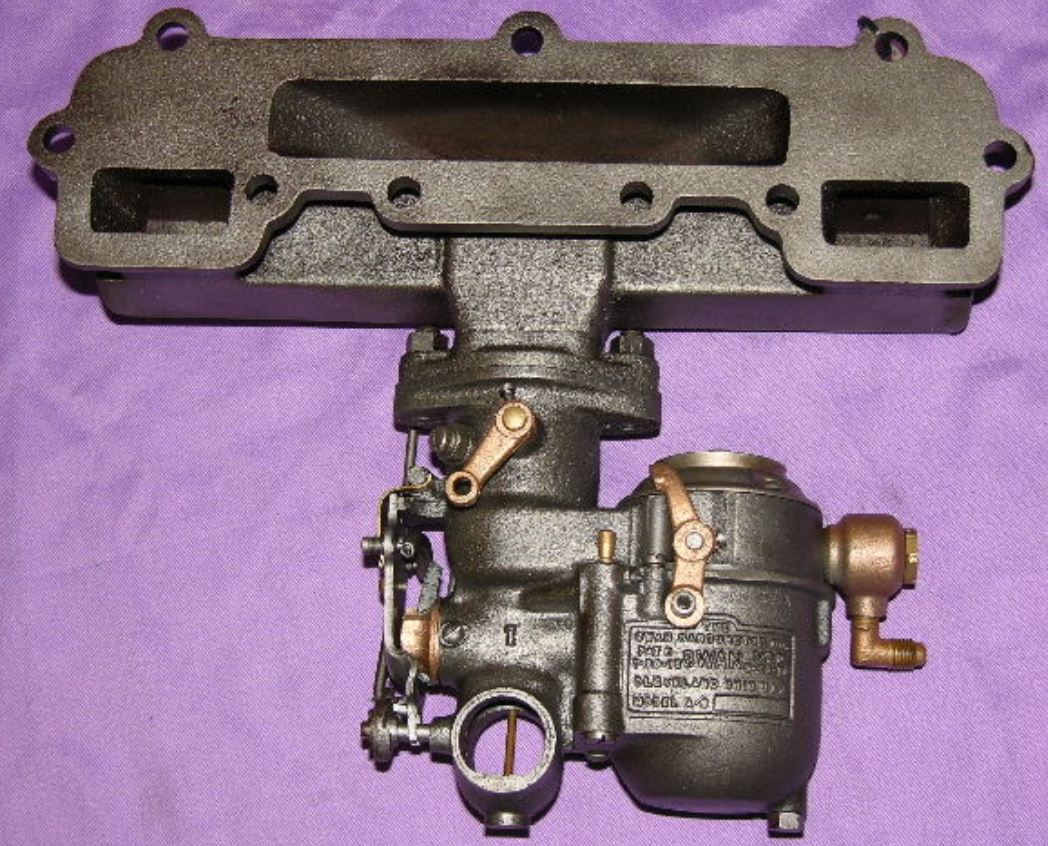
1925 Hudson rebuilding the Carburetor.
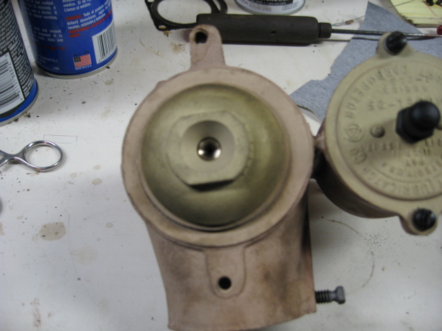
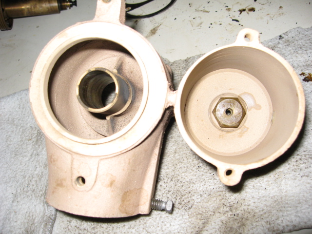
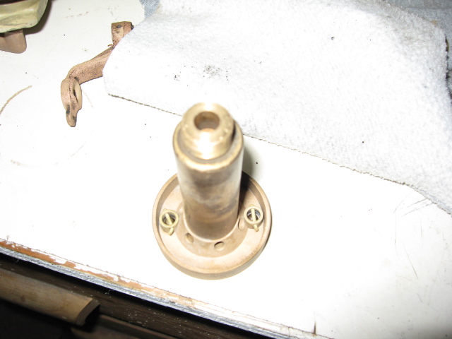
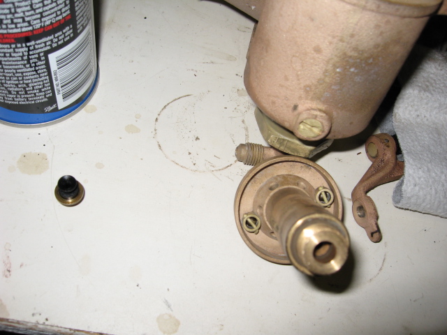

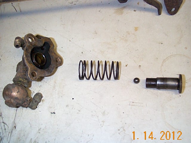
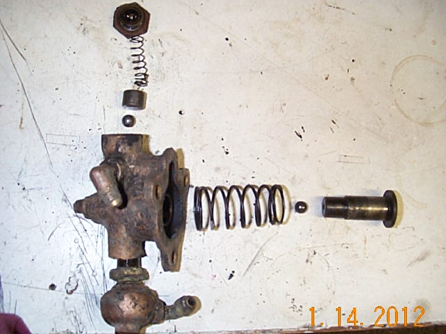
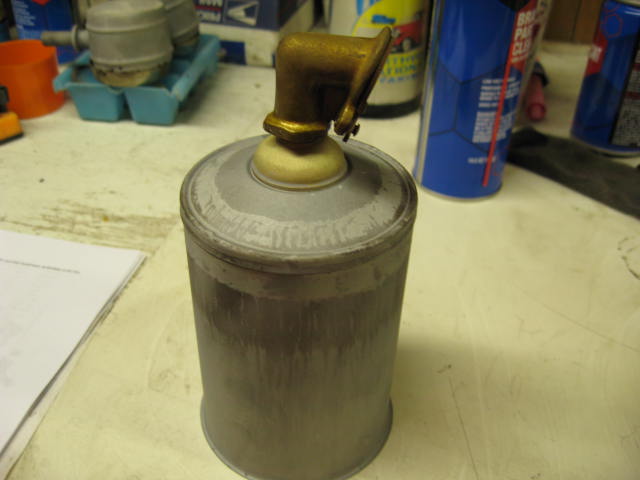
Rebuilding fuel pump.
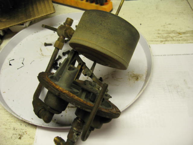
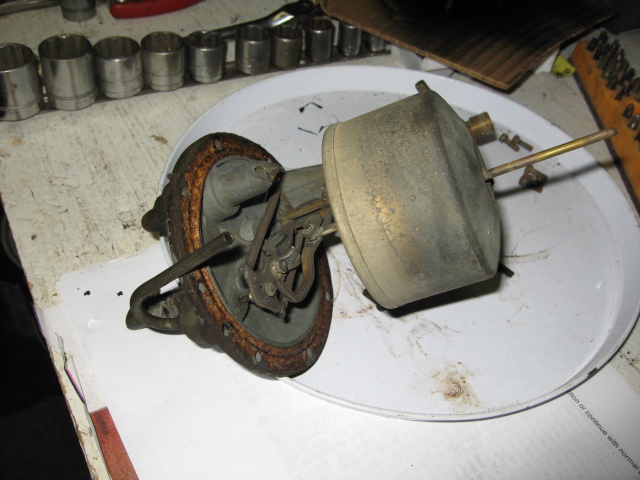
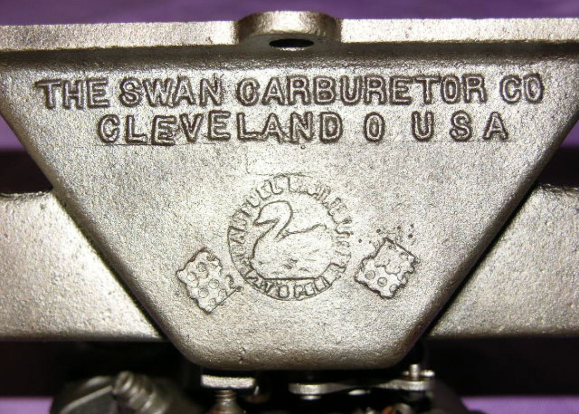
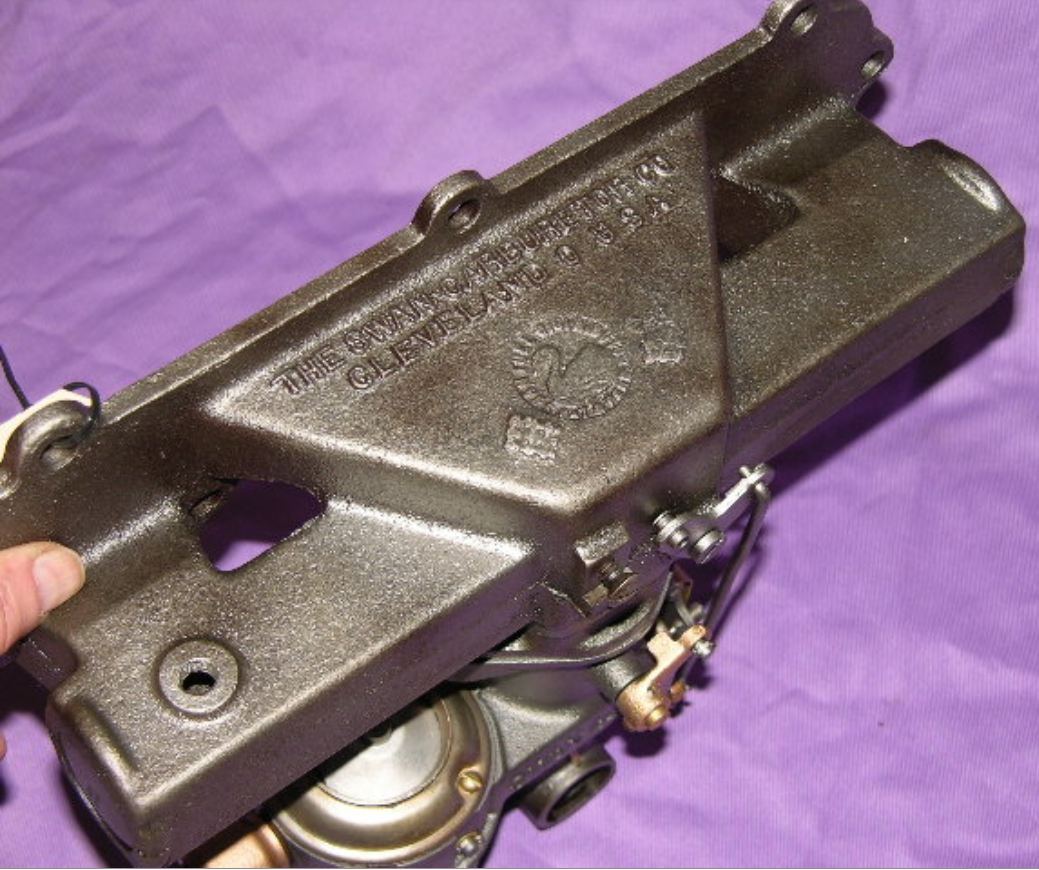
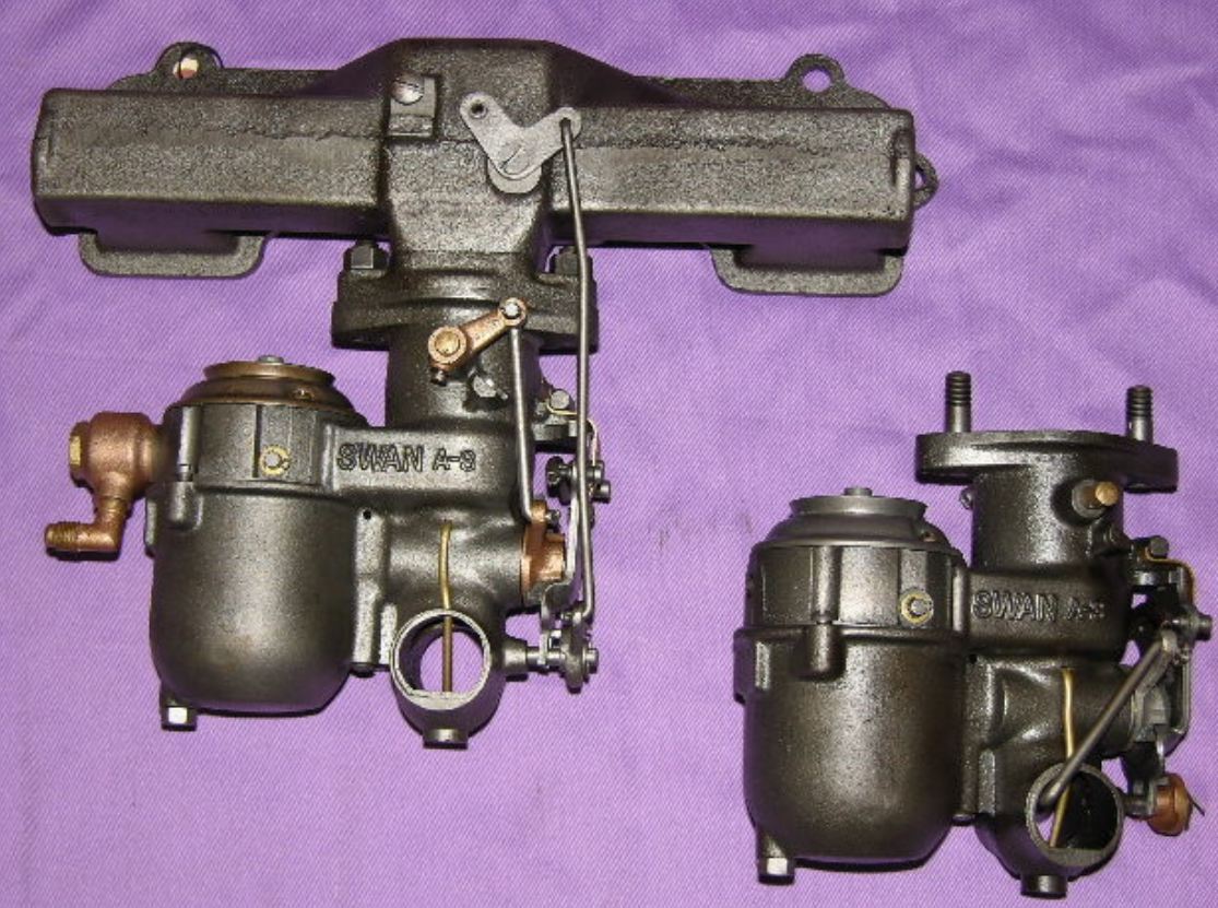
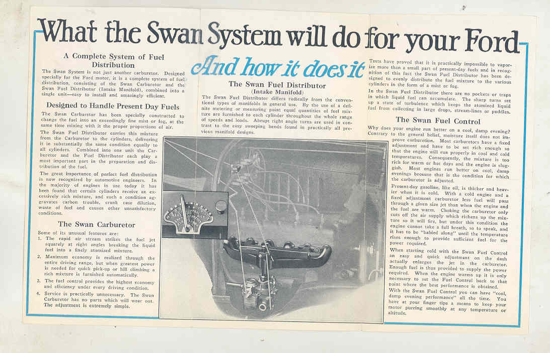
I found a very RARE Swan carburetor and intake manifold for 1924-26 Hudson
Super-Six models.
Swan was famous for their Model "T" Ford racing carbs. Appears
to be N.O.S.
I got a 2nd Swan A3 carburetor with a 1 5/8" throat with
narrower stud mounts.


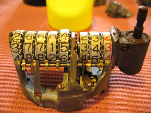
1925 Hudson rebuilding the Speedo. That pot metal really loves to expand.

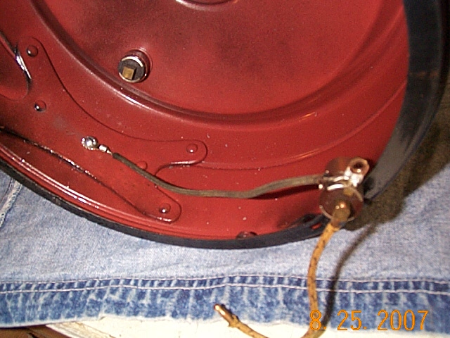
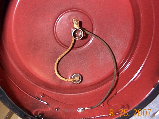
Click here to see what I have learned about Stoverlite tail lights.
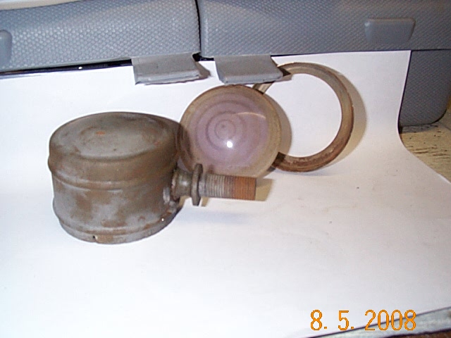
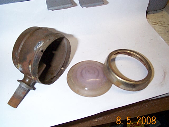
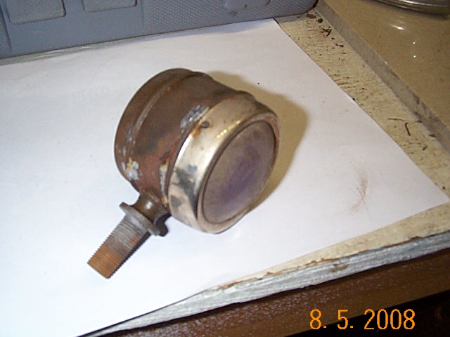
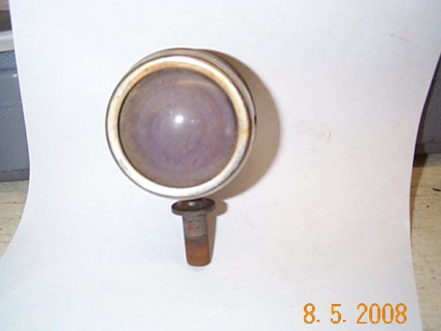
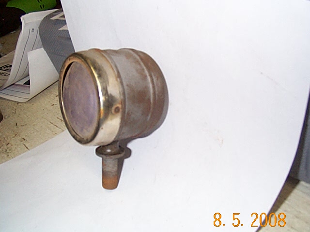
1925 Hudson cowl lamp repair. They are rusted through on the bottom, so I lead filled the holes.
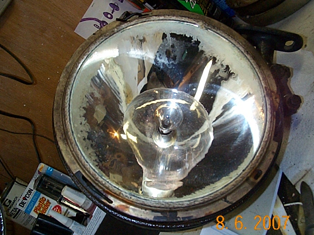
1925 Hudson Head Lamps. They are like the 37, but simpler. Out of 5 I got 2 good reflectors.
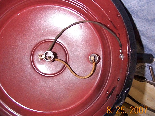
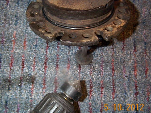
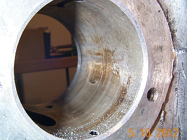
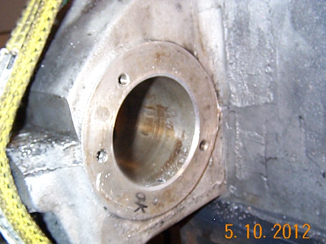
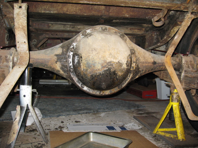
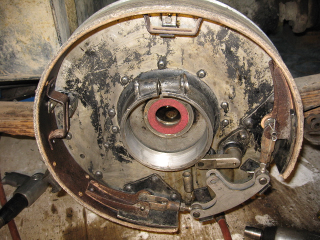
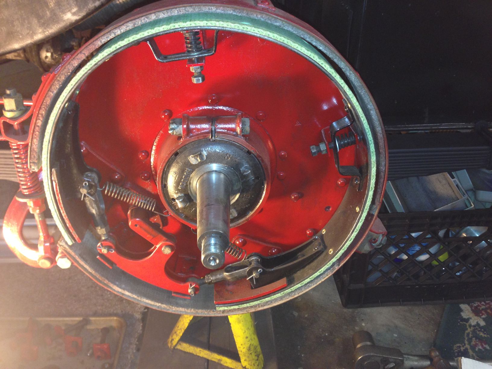
1925 Hudson Rear Axle, doing the brakes. Putting in new felt axle seals. Pulled pumpkin cover and cleaned out 50 + years of filings.
I did glue a magnet inside the housing to catch what I might have missed, but forgot to take pictures of inside.

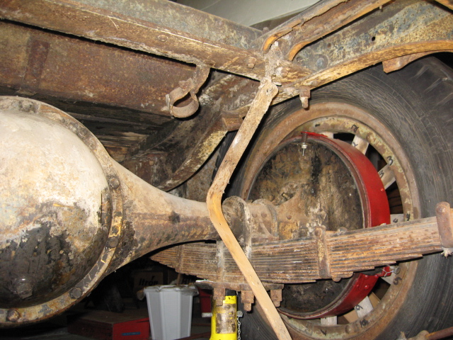
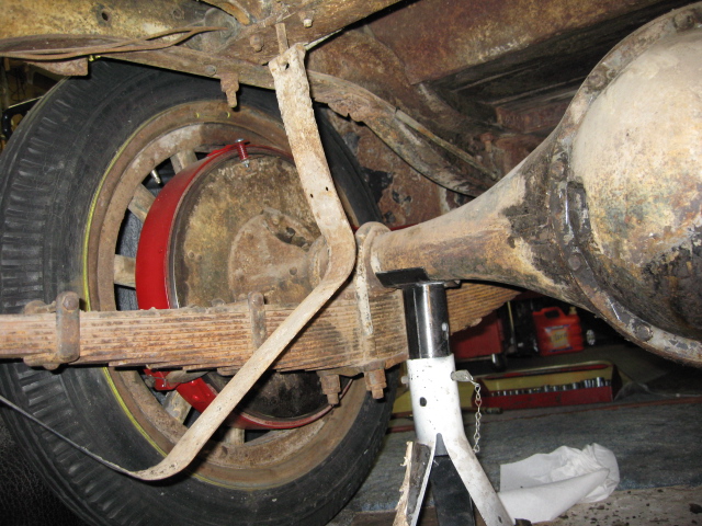
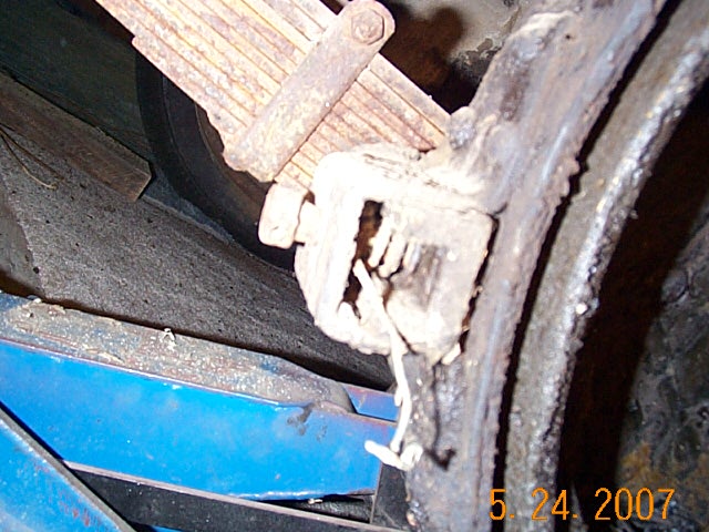

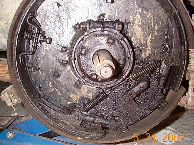
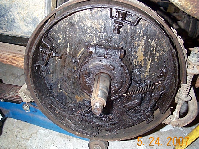
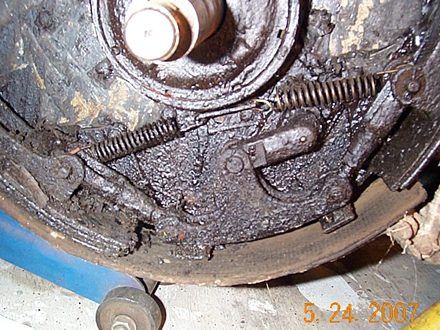
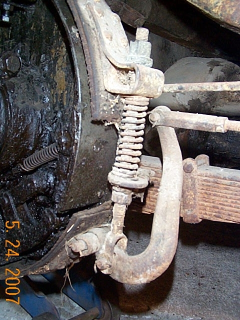
New felt seal installed, cleaned up and going back together.
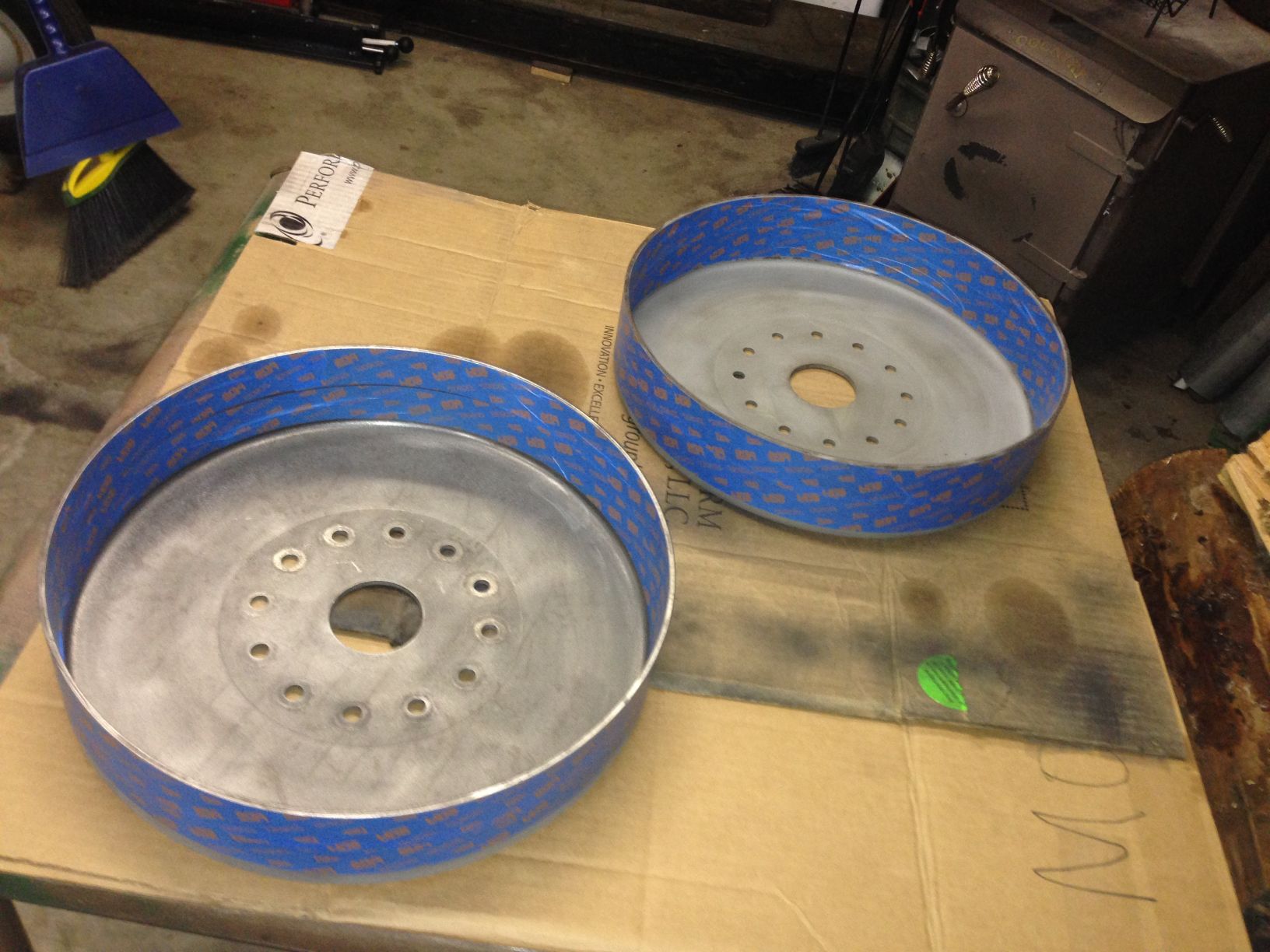
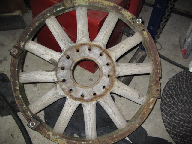
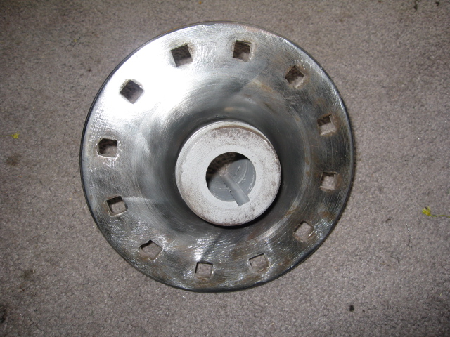
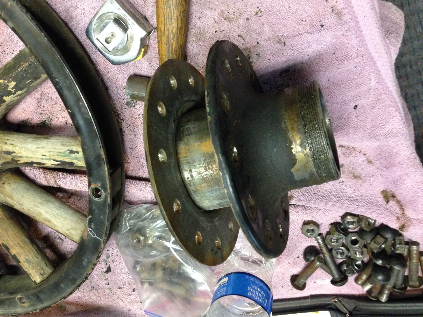
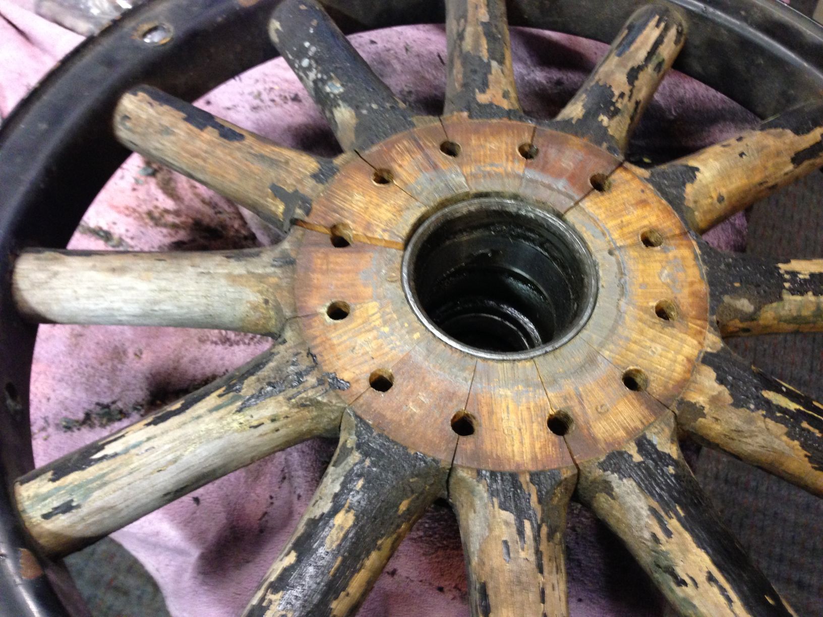
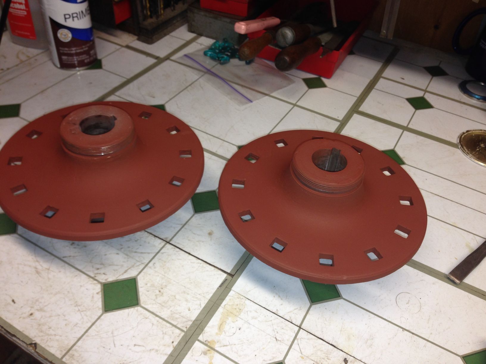
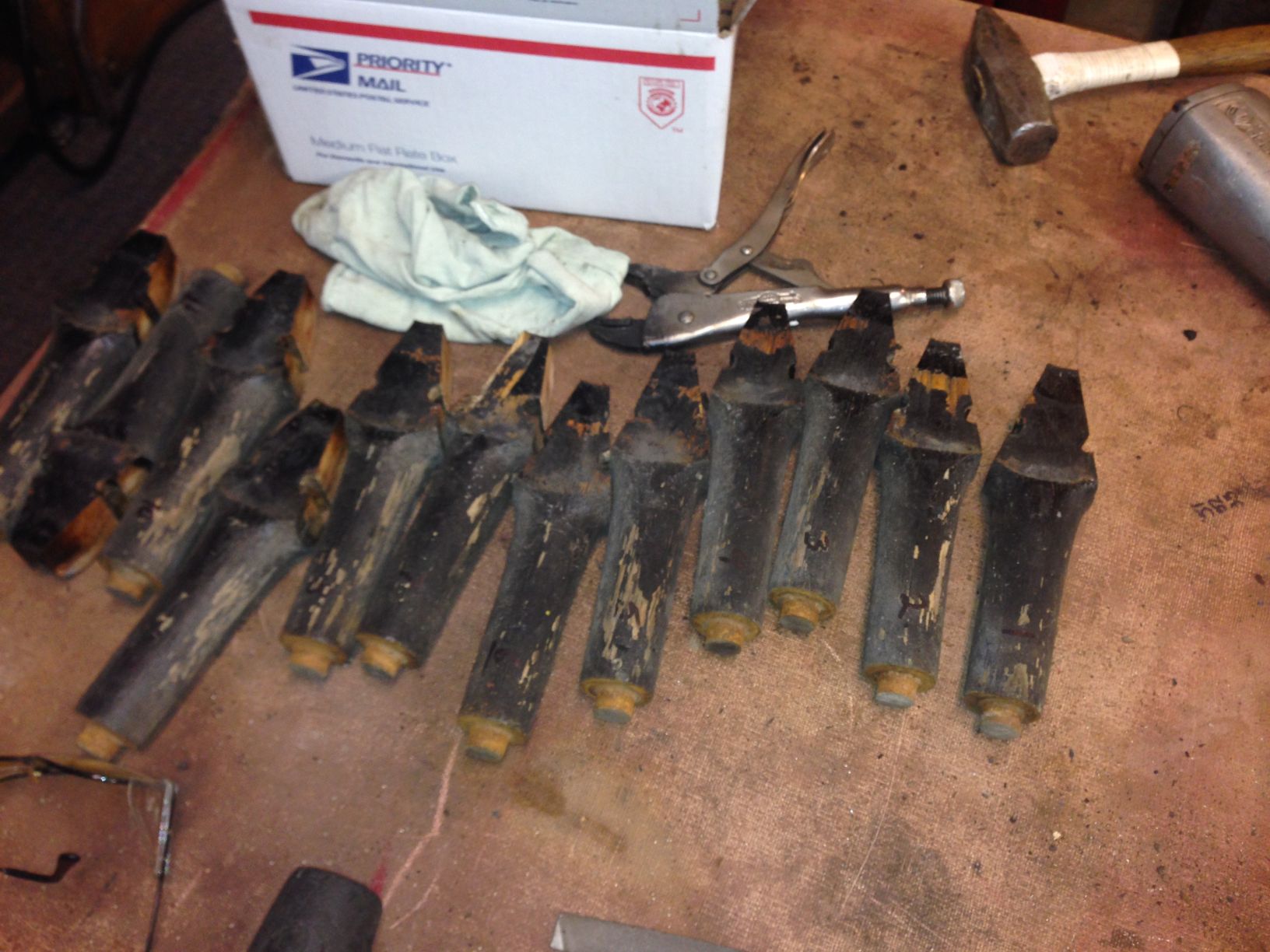
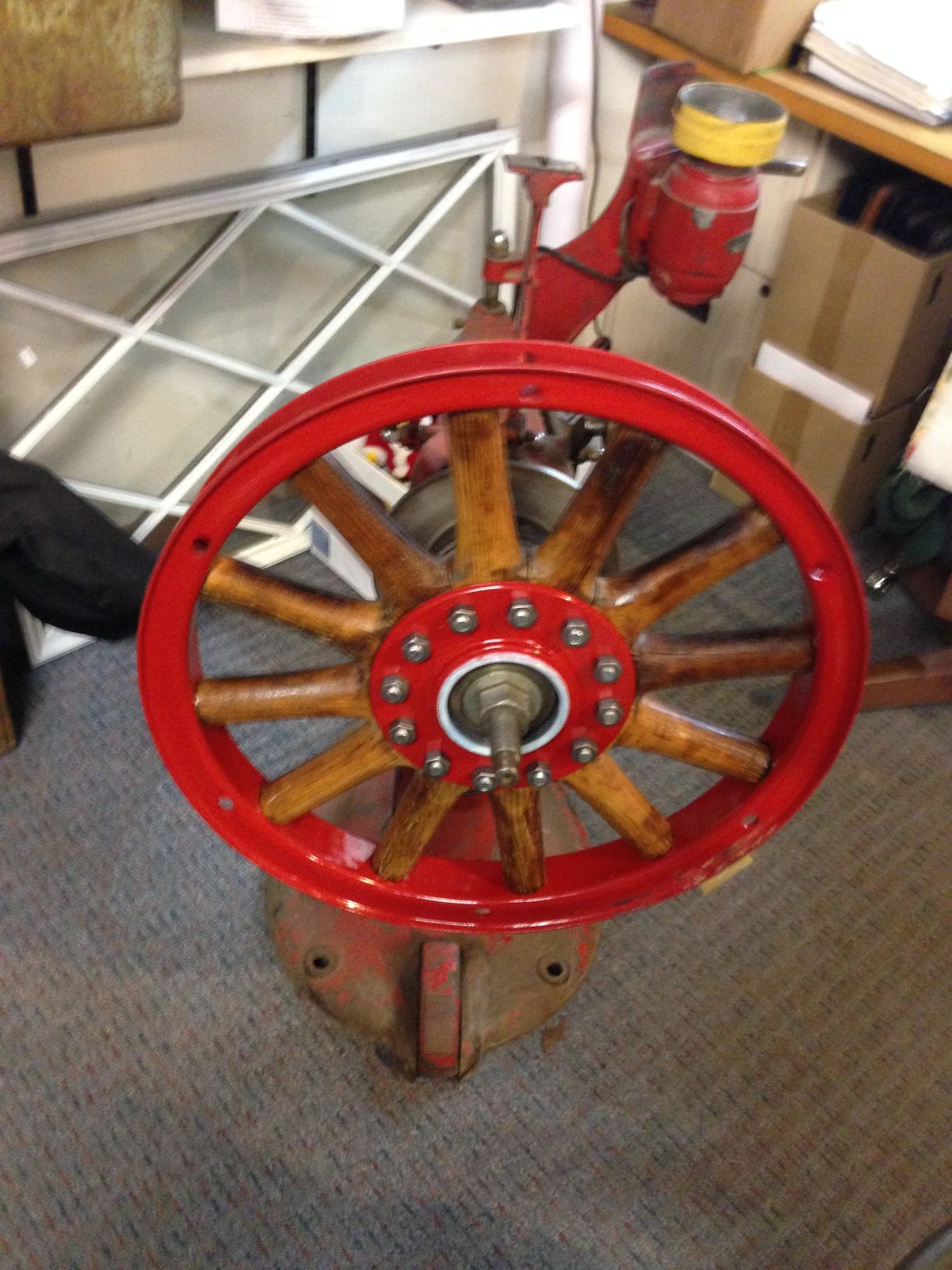
1925 Hudson making a new rear wood spoke wheel from a front one.
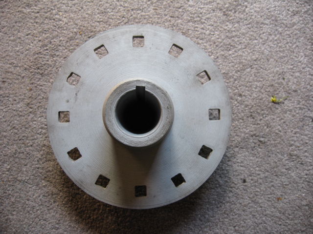
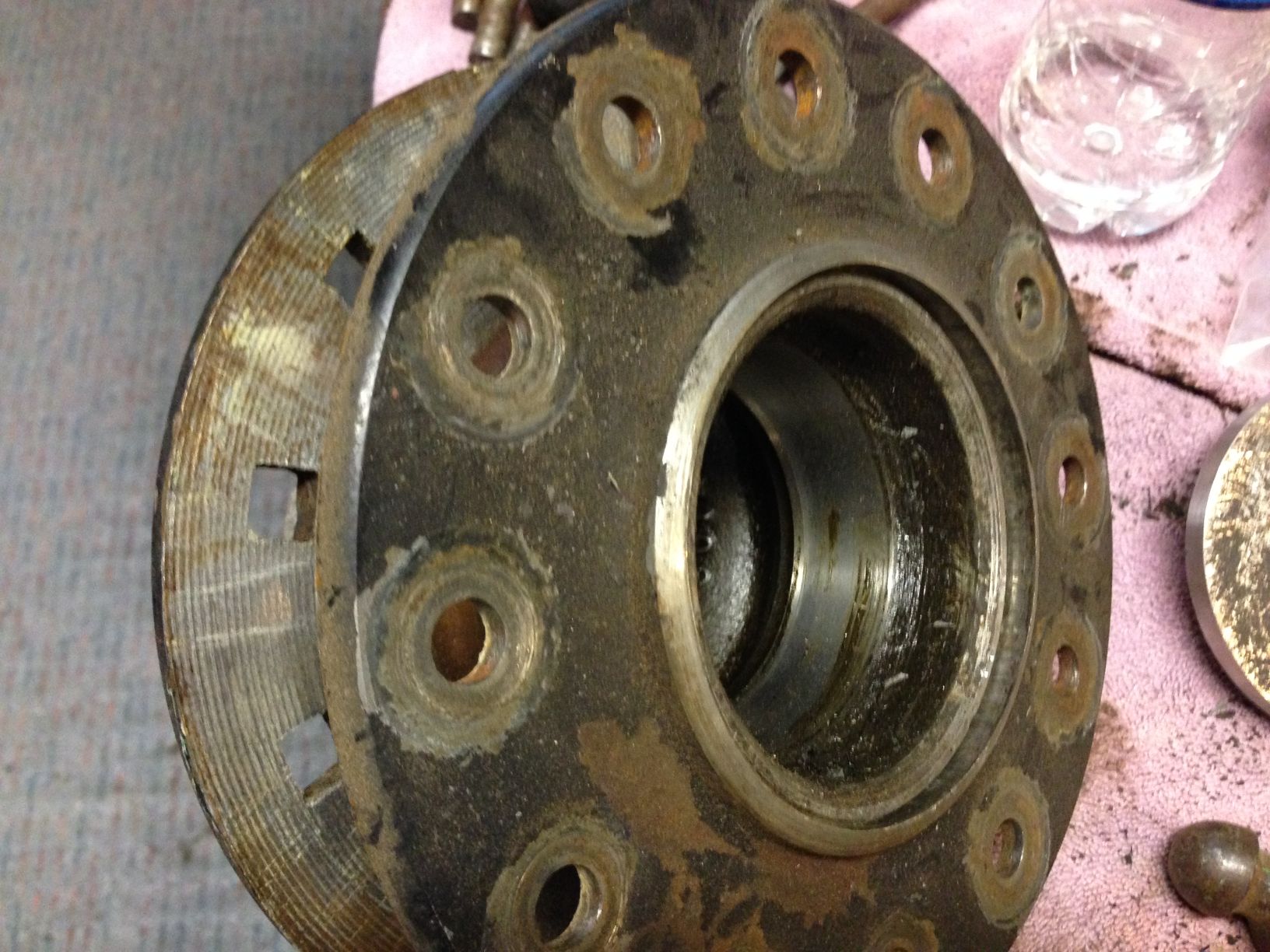
The spokes are from a front wheel with bearing hub removed. The hub in the second picture is the rear.
I did not get a picture of the final hub. I shrunk a sleeve on the hub the diameter where the spokes contact.
Front hubs are larger in diameter where the spokes contact the hub.
Then pressed it into the front spoke assembly. Went .030 larger than the original front hub to make up for spoke wear.
Nice tight wheel now.
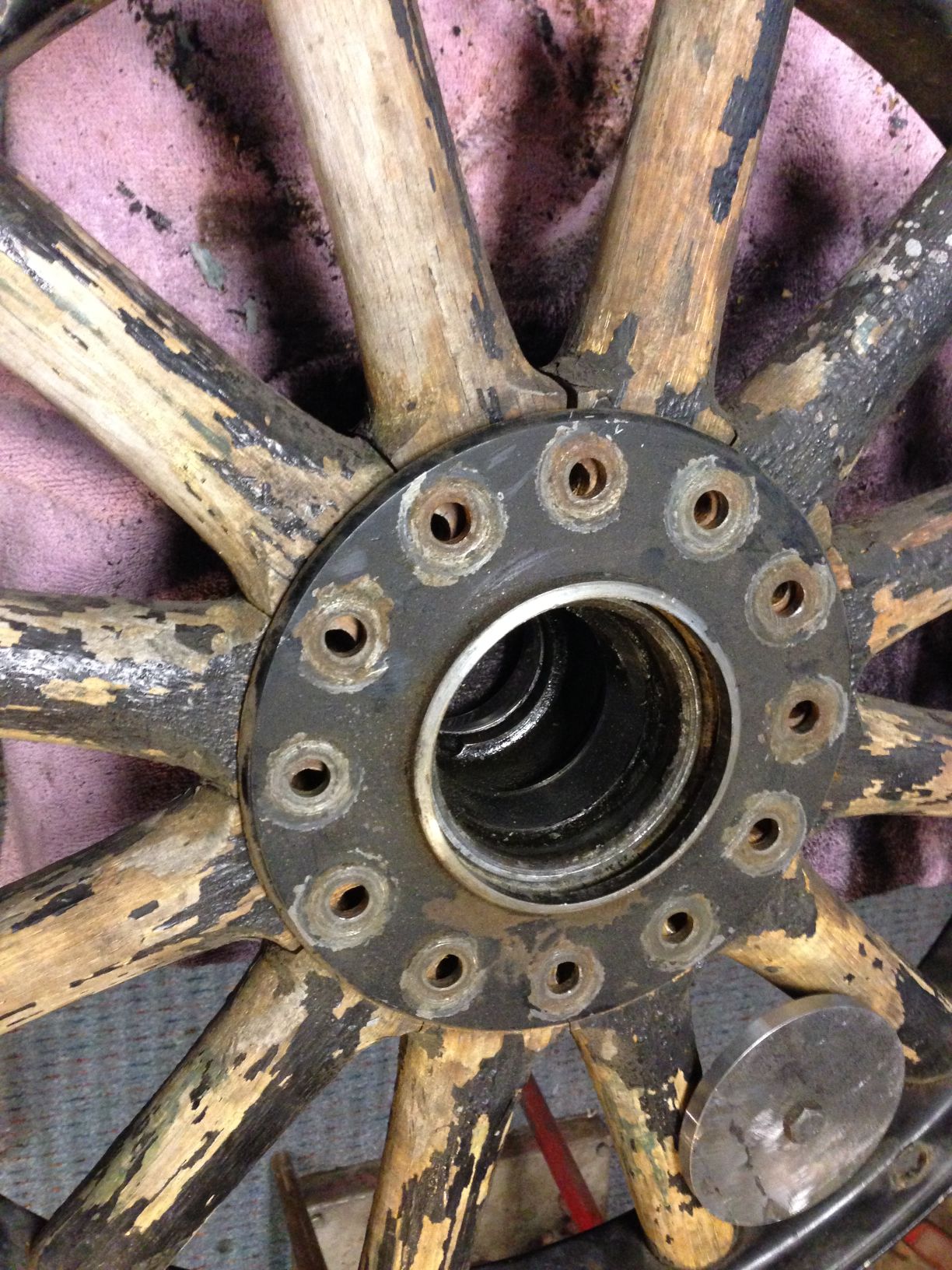
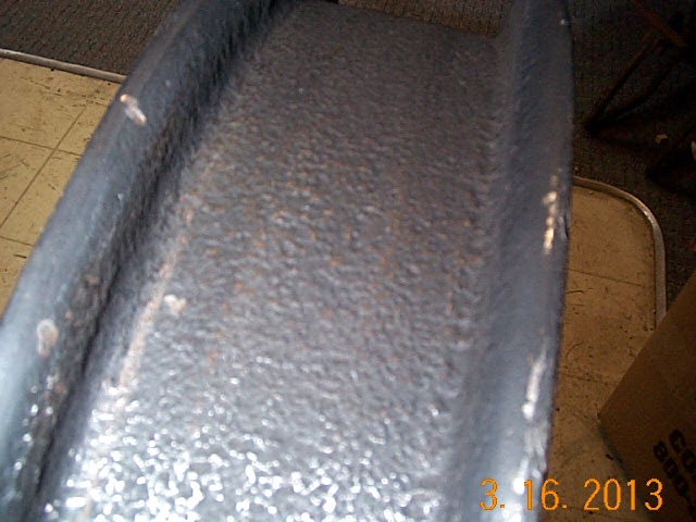
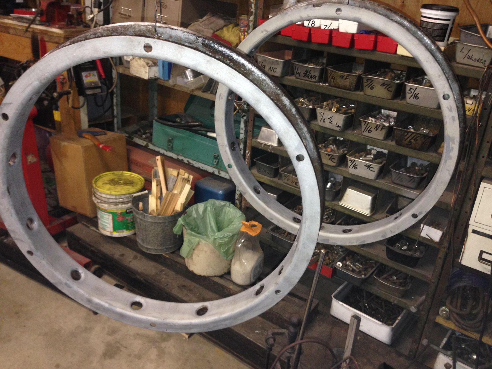
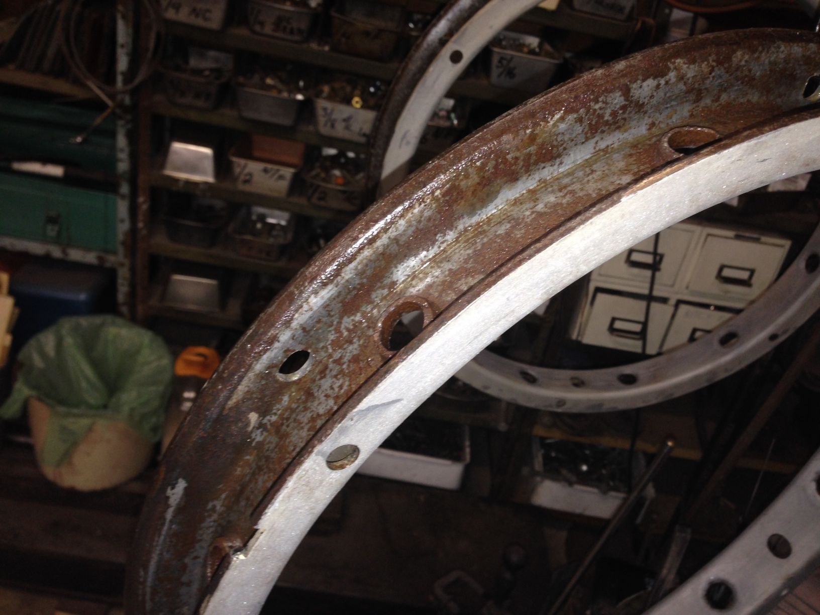
The rims were a bit rust pitted. I used leftover gas tank sealer to coat them.
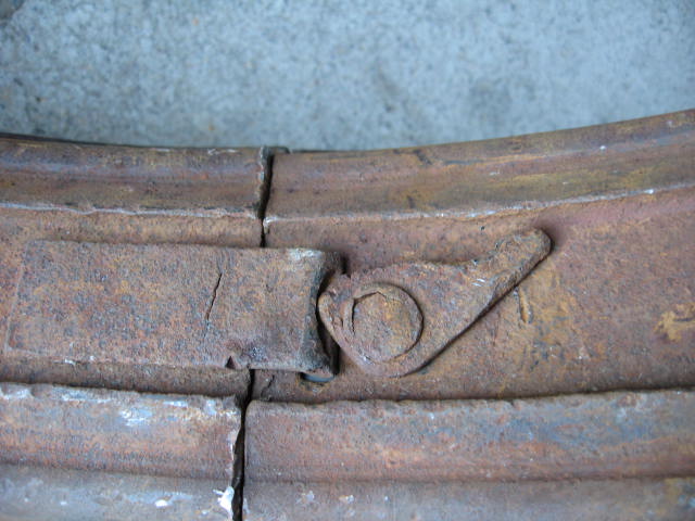
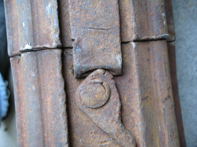
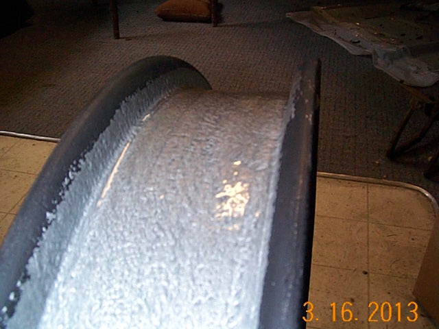
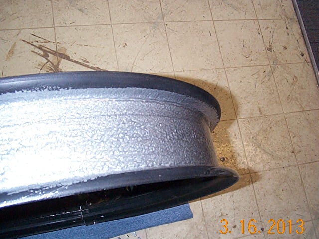
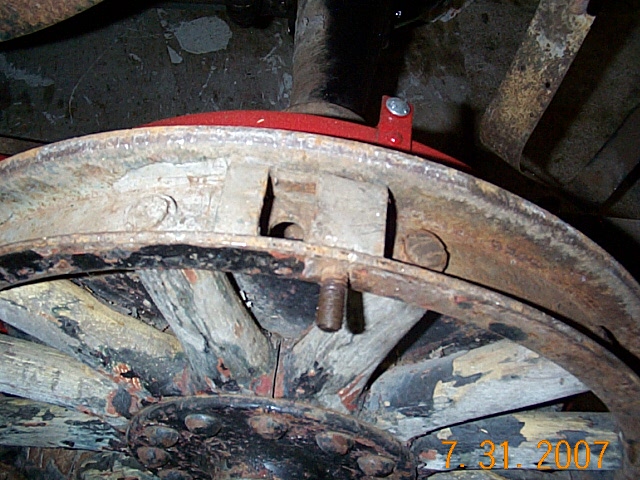
Winter 2014. I found that the other rear wheel, outside ring was loose on the spokes so I took to repairing that wheel.
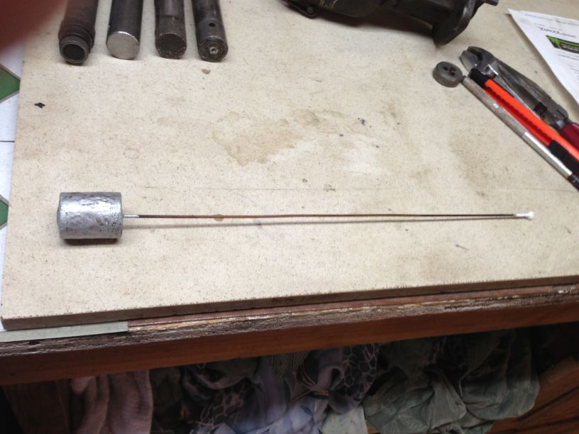
I learned about what all you can do with a vacuum pump while I was pouring new lenses for my Stoverlite.
I had 2 broken spokes. Mixed up a batch of epoxy and glued them.
Then put into a vacuum chamber and infused the glue into the spoke, also removing all the air trapped in the glue while mixing.

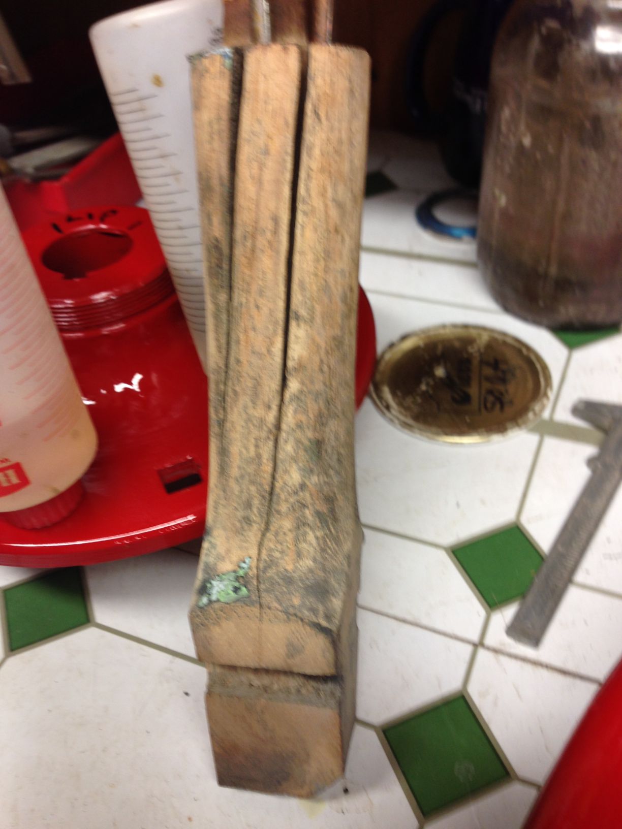
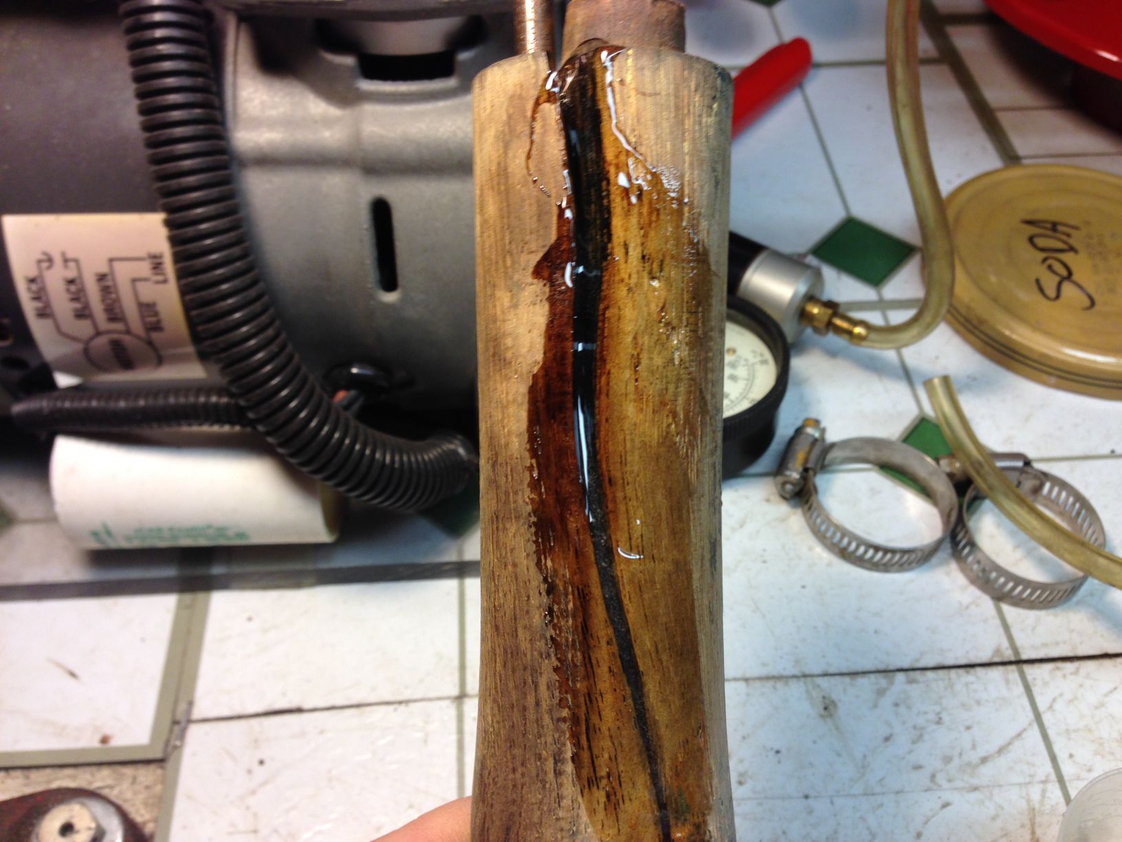
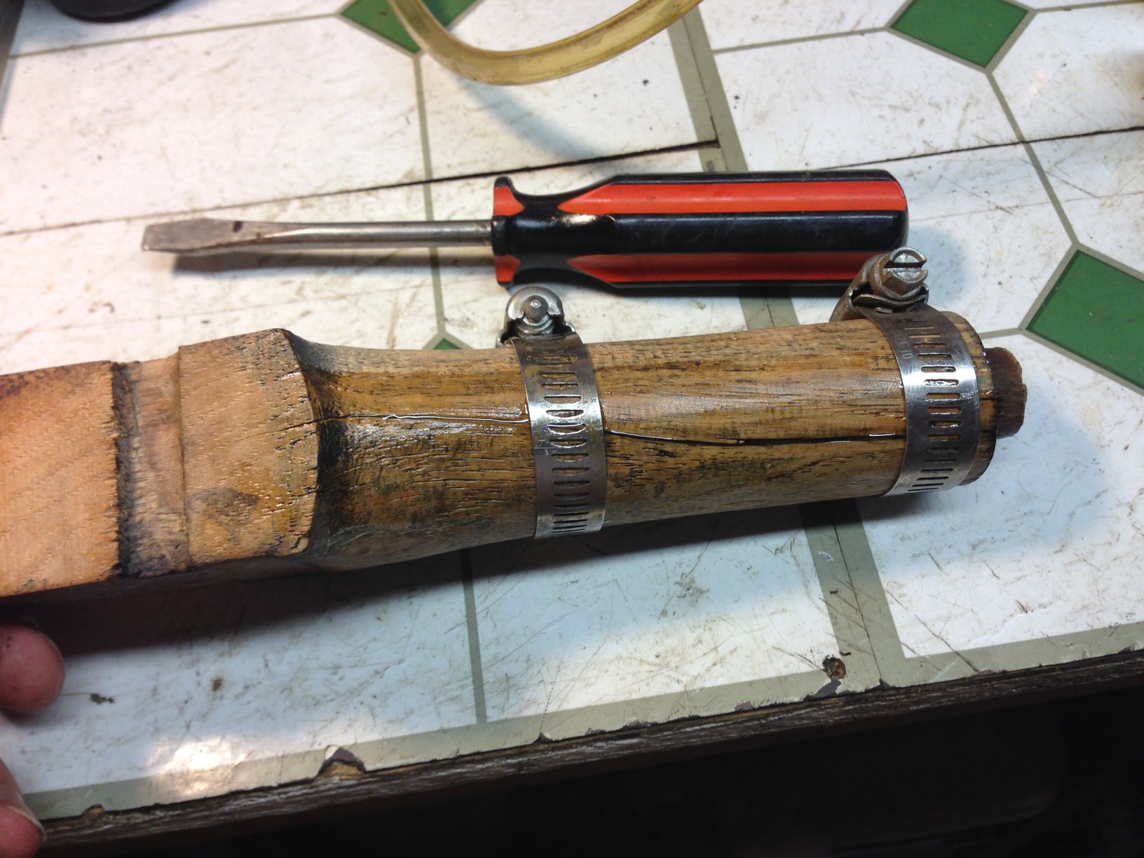

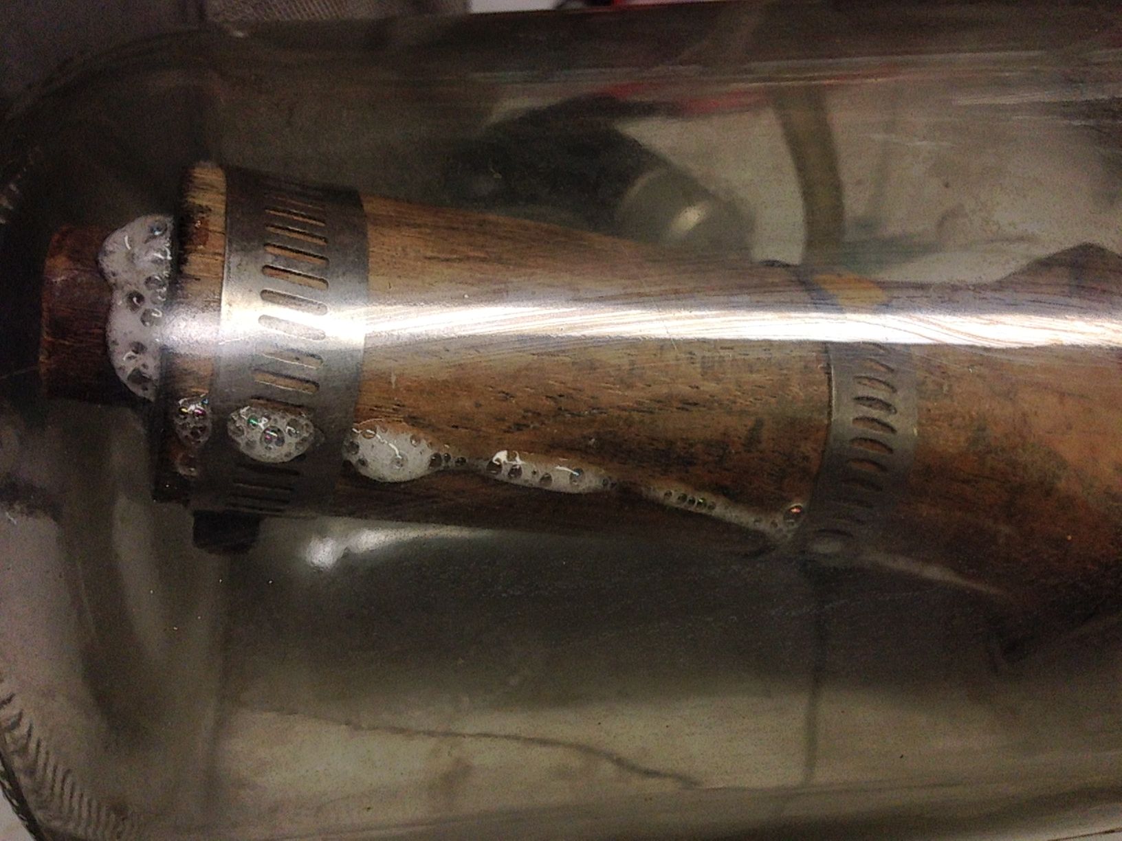
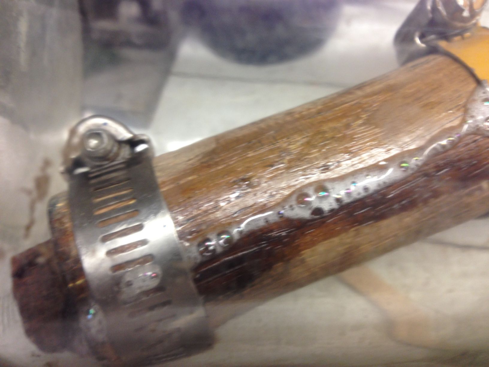
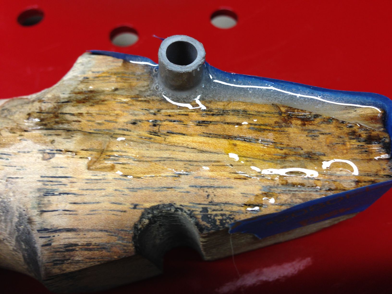
Spokes are repaired and now infusing them with Spar Varnish.
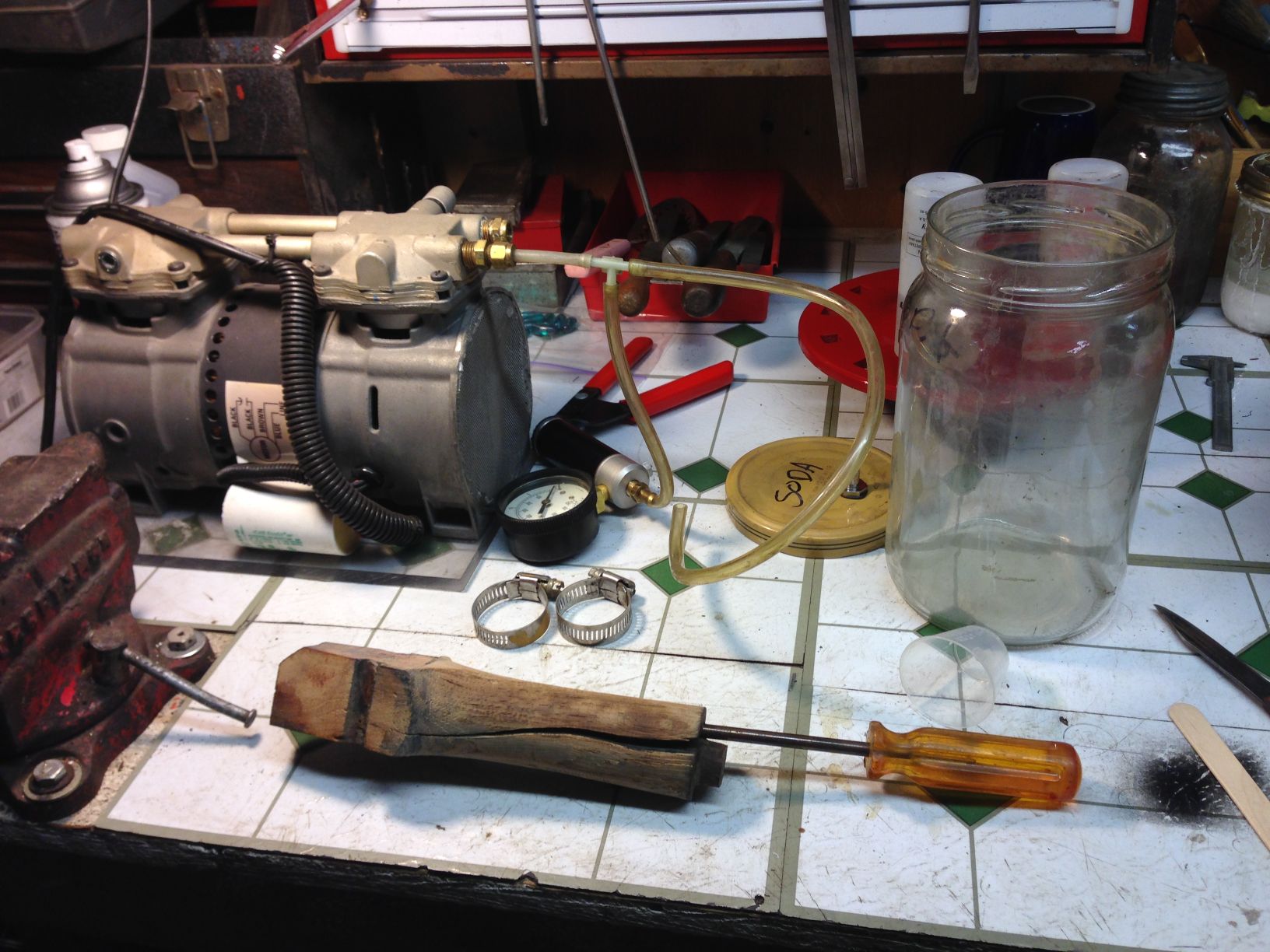
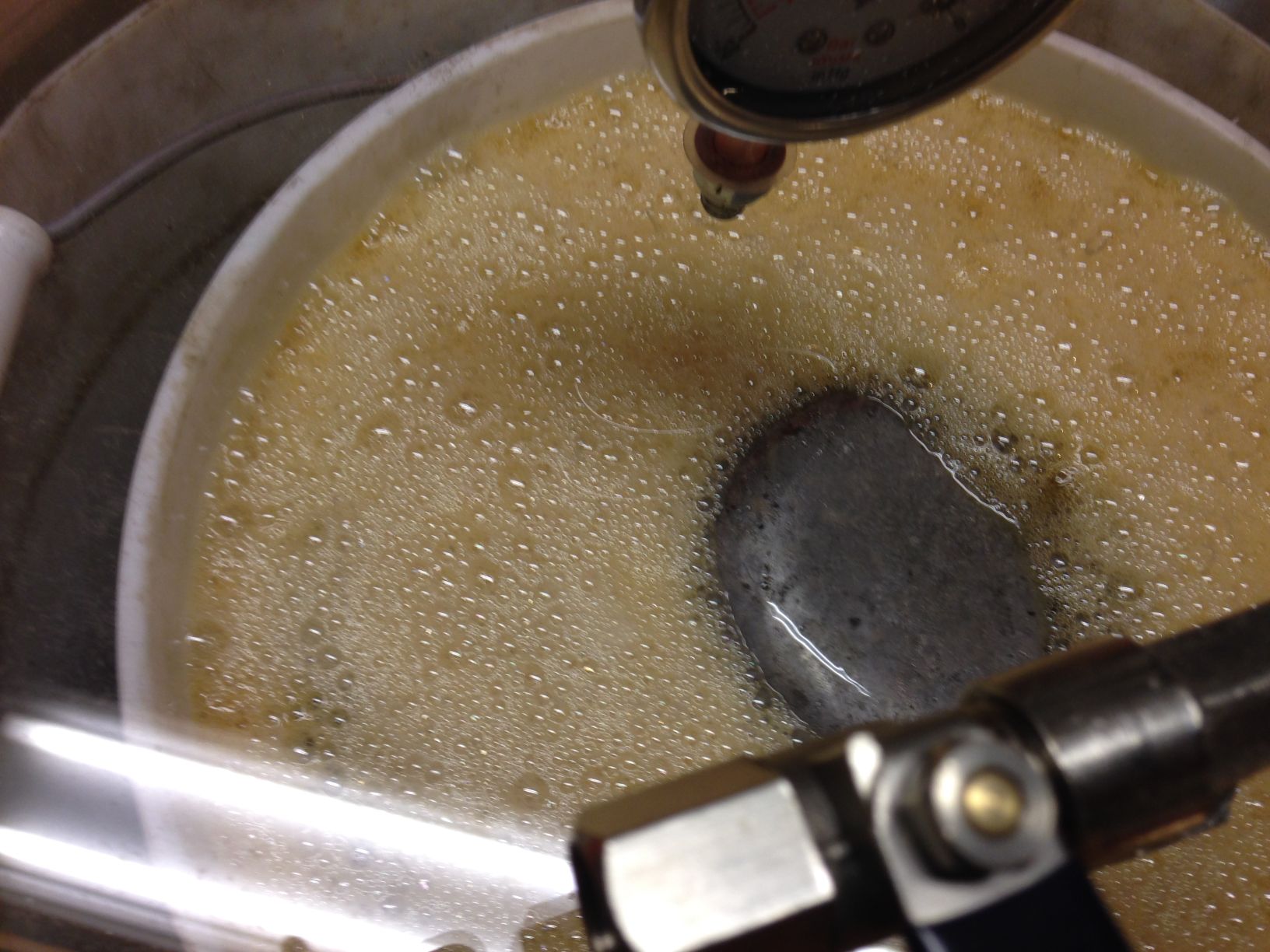
Pictures below show how the air is sucked out of the spoke and replaced with the Varnish.
I had 2 pickle jars so I could do 2 spokes at a time.
If you have really bad spokes you can use a very liquid epoxy and infuse them with that, they will last your lifetime and your grandkids.


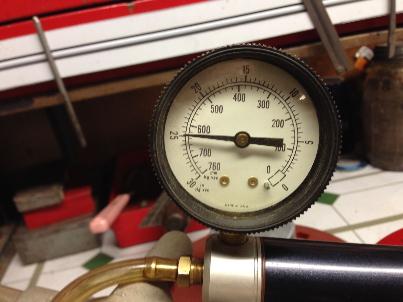
The most vacuum I can pull is 25 inches. After research I found the higher in altitude you are the less vacuum you can pull.
I am at 2300 feet so this is about right on a good day.
I got this 5 gallon chamber from Amazon. It is nice, came with all you see including the hose.
The shut off valve on the pump side is nice because you can leave the tank for a day without having to run the pump all the time.
I ended up leaving them soak for 2 days with an occasional run of the pump.
This is a full set of spokes. What you see in the foam is a weight on top of a screen that holds the spokes down.
Takes about an hour for the initial air to be removed. As you see I have a bucket in the chamber, takes less product to infuse.

I am actually doing 2 rear wheels, one for a spare to mount on the back of the car.
Pictures of hubs, both set of spokes, outside rims before I starting sanding.

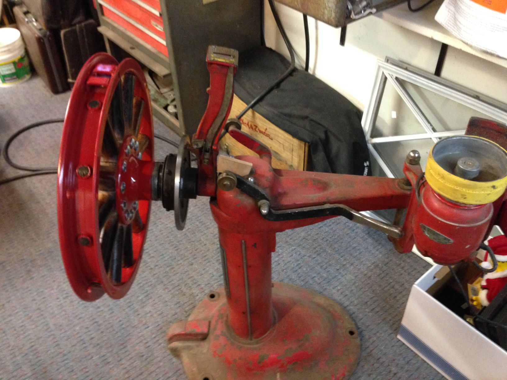
I bought a antique John Bean wheel balancer summer of 2011.
I have an extra spoke wheel for my 1925 so I balanced it, then mounted the tire rim assembly on the wheel and balanced the assembly.
I have the Wall Chart on how to use a Bean wheel balancer in my Tech area.
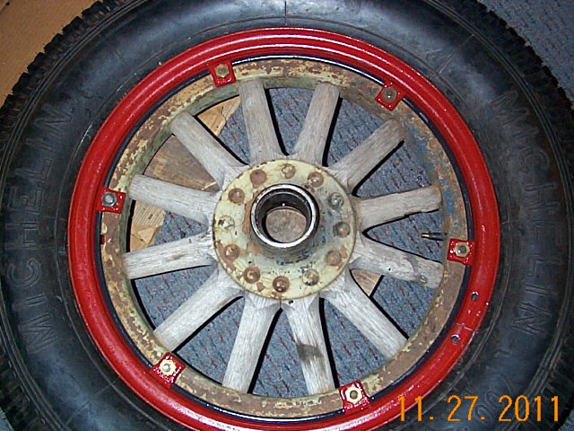
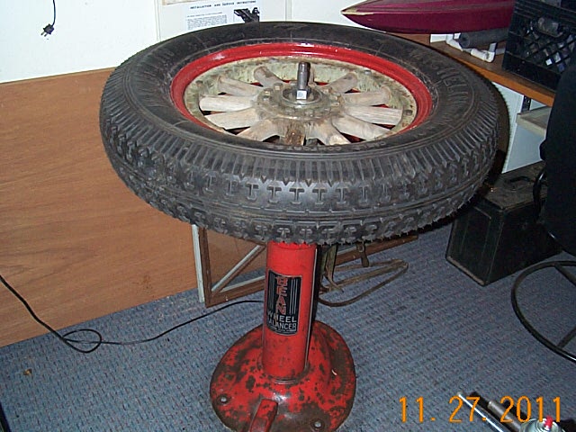
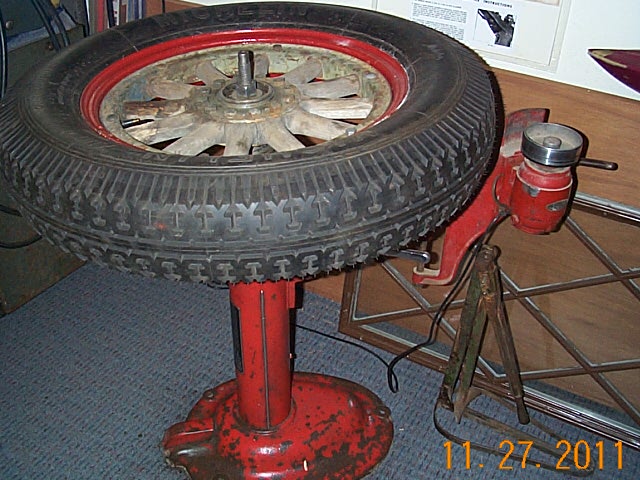
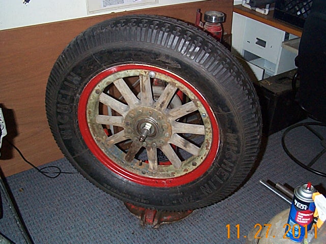
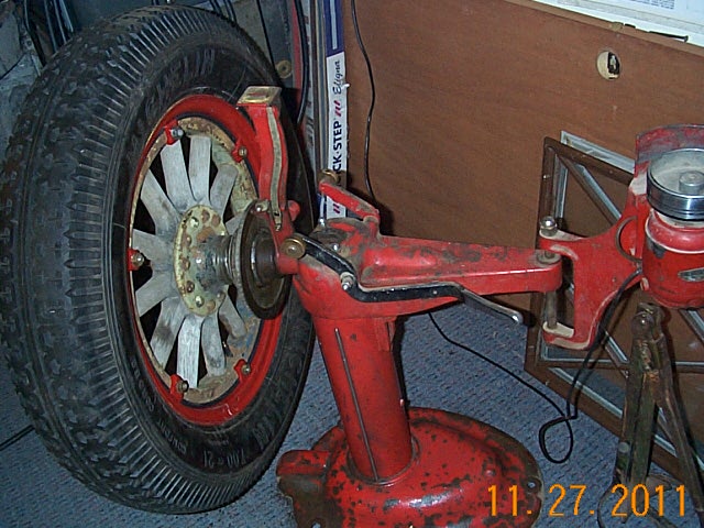
2014. Balancing the wheels before putting on the tires with rims. They took about 4oz which I welded steel weight on the inside.
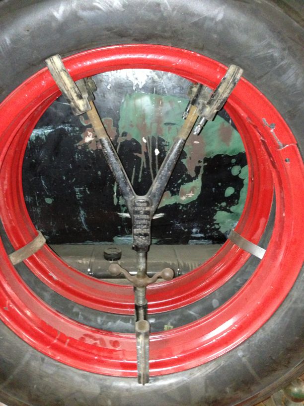
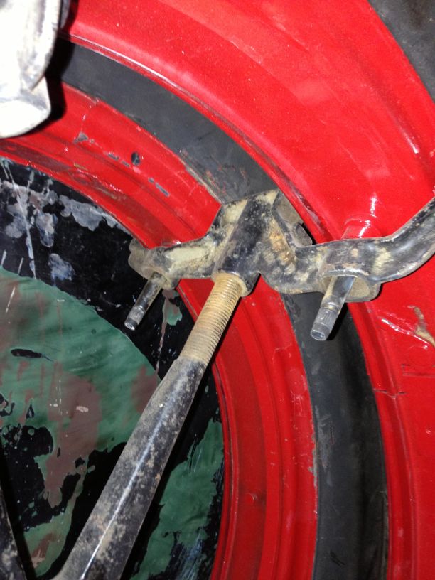
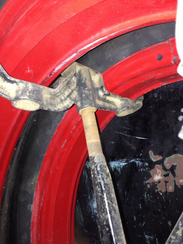
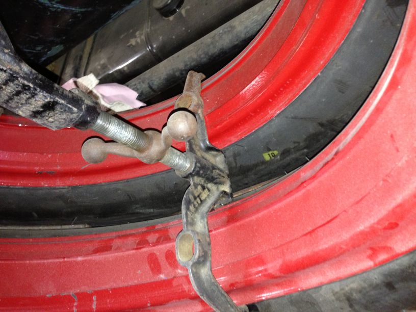
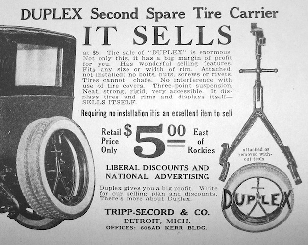
Found a Tripp Secord Duplex Tire Carrier. It is for 2 different size wheels, but it works.
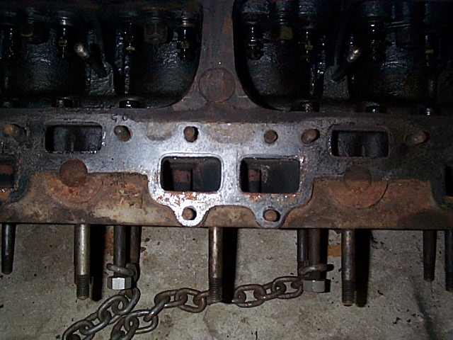
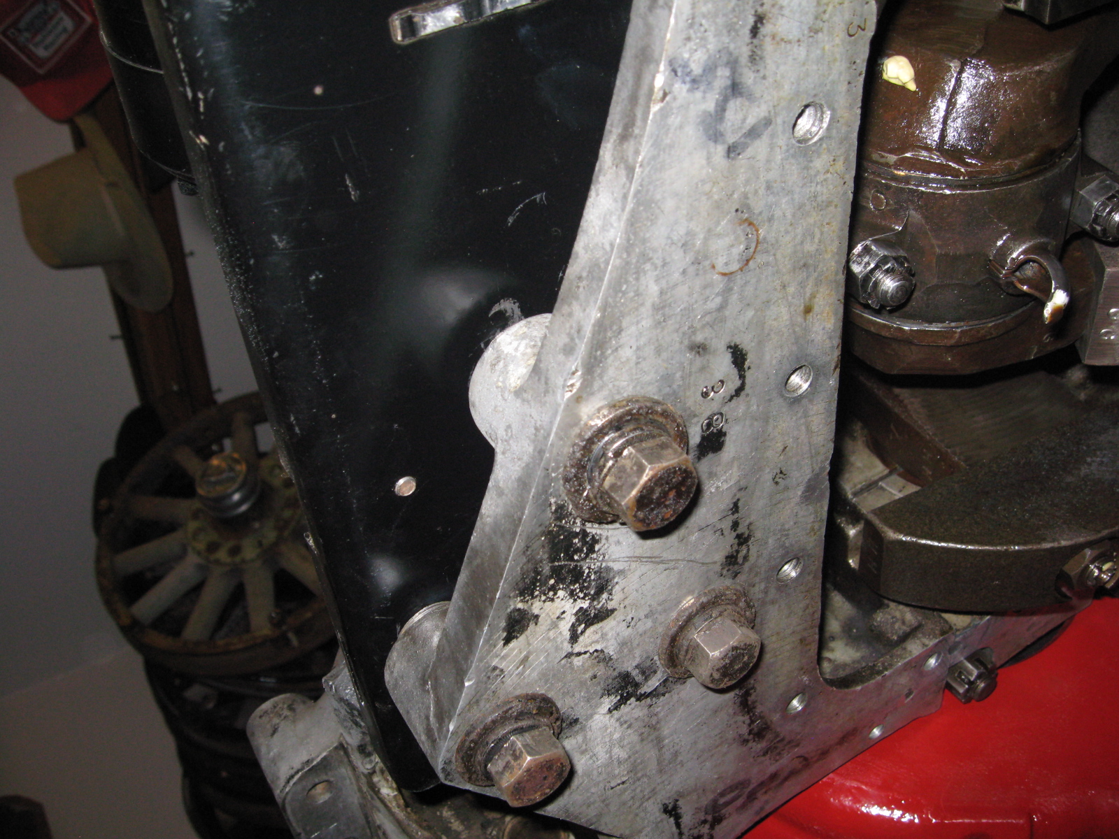
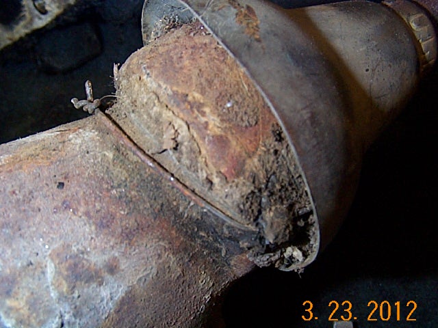
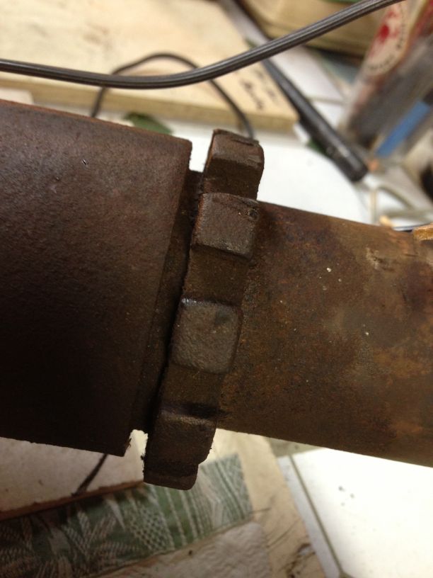
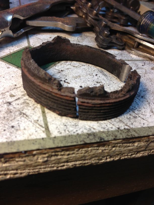
Guru Geoff Clark said don't mess with the gland nut that holds the header pipe in the manifold. When the master speaks, LISTEN!
With the following pictures I will show you what NOT to do. I figured I could heat up the manifold red hot and get the
gland nut to break loose.
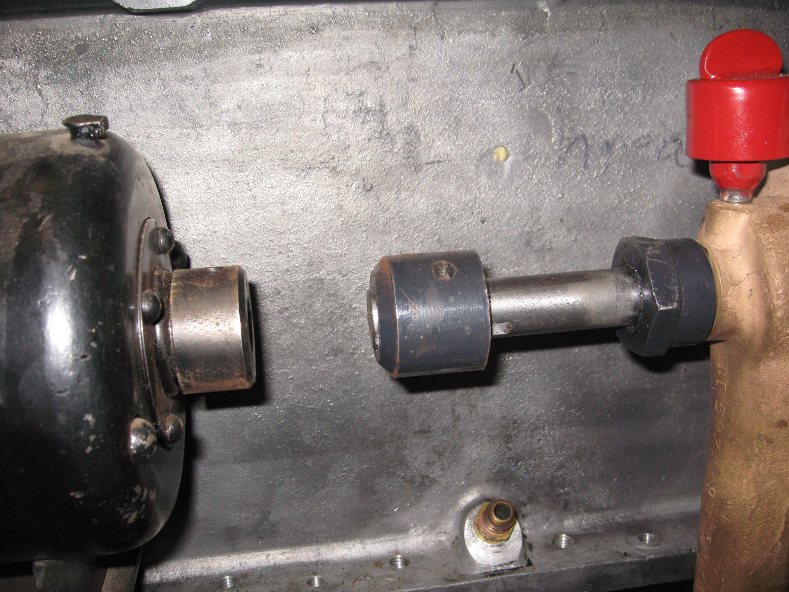
It breaks alright, breaks the lugs right off. As you can see from the last picture there is very little cast iron holding them to the threaded sleeve, last picture.
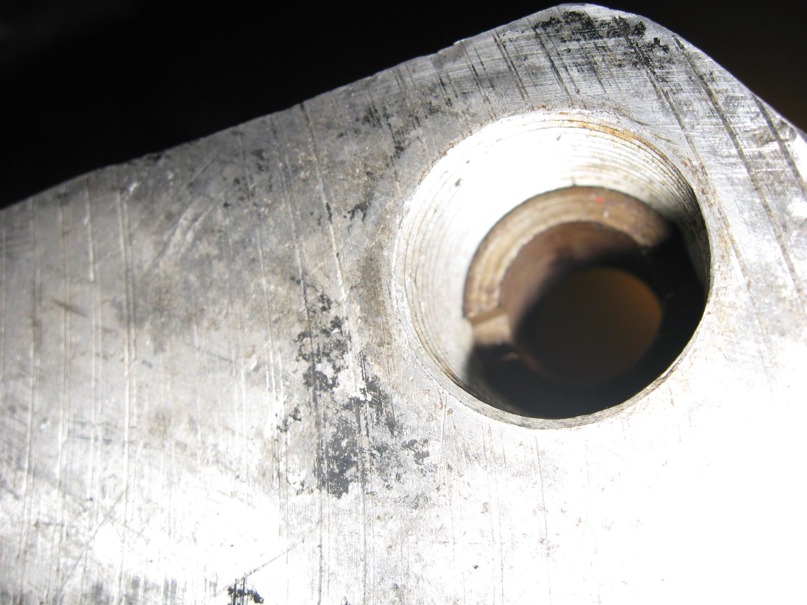
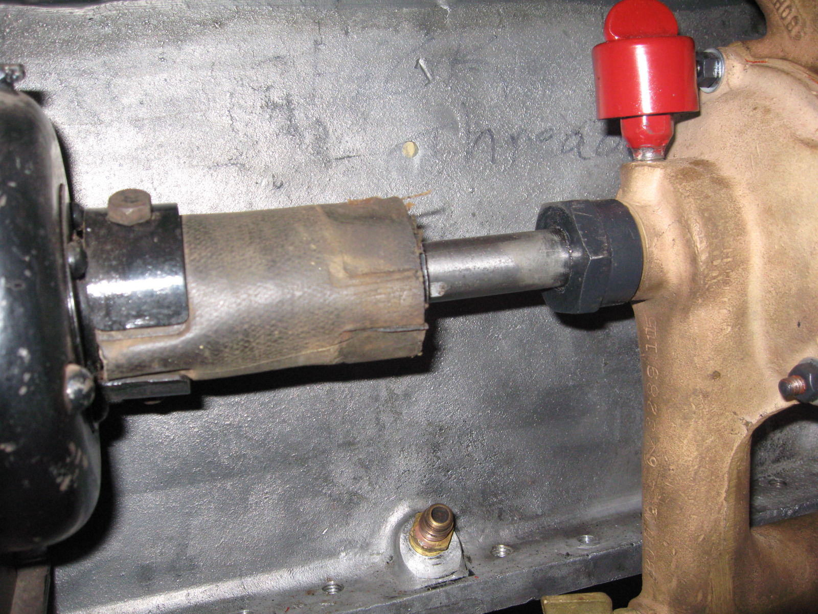
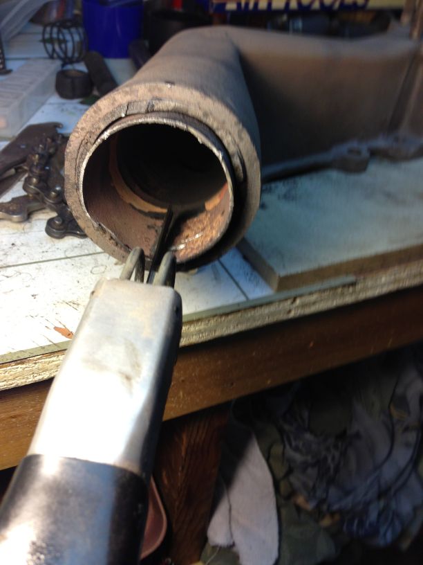
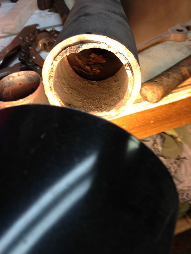
After learning my lesson here is how I got it apart. I used an air saw to split the inserted pipe.
4th picture, used a Dremel with small carbide burr to cut down to the threads.
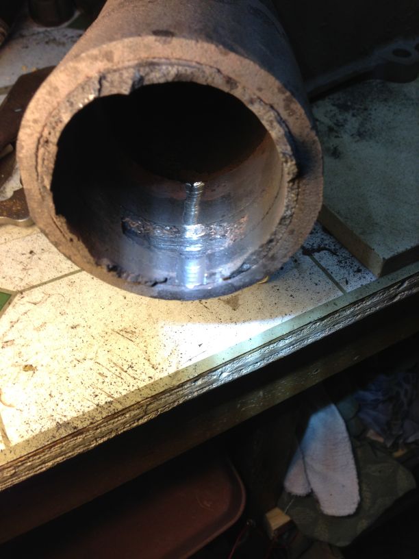
This also shows the flat gasket material partially missing between the end of the nut and casting stop inside.
Final picture shows the removed nut with all the lugs broken off, (yes I kept trying to screw it out with a spanner and pipe wrench).
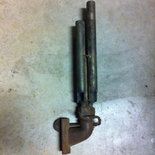
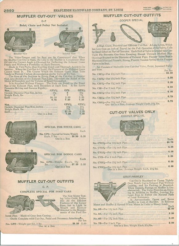
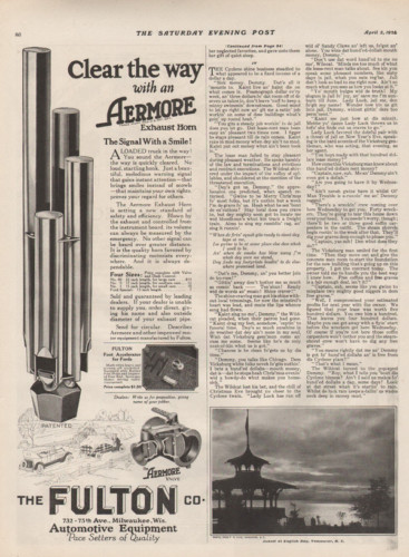
I have an Aermore exhaust horn I want to install.
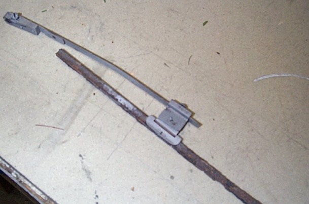
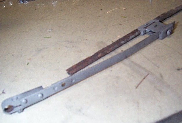
Wiper that was on the car.
On to Page 3 Interior and Body Work
Back to Page 1 of pictures.